
Forging the Φ2440 mm GH4169 Turbine Disc: Full-Process Simulation and Control
China’s largest nickel-based superalloy turbine disc — a Φ2440 mm GH4169 (Inconel 718) forging — was produced under a coupled finite-element and microstructure model. Heating, transfer, deformation, cooling and press load were each brought under numerical control, and the dissected disc confirmed the predictions.
GH4169, known overseas as Inconel 718, is a precipitation-strengthened wrought nickel-based superalloy. Its combination of creep, fatigue and corrosion resistance at 650 °C with high overall mechanical properties has made it the workhorse disc alloy for aero engines and heavy-duty gas turbines. As those machines grow, so does the disc — and every increment of diameter multiplies the forging risk.
Supersized GH4169 discs start from very large ingots. The melt route is vacuum induction melting (VIM) plus vacuum arc remelting (VAR), or the triple route VIM + electroslag remelting (ESR) + VAR. After multi-stage homogenization and several cogging heats, the bar is blanked and then open-die forged and die forged into the disc. For a disc of this class, those forging operations decide the quality and the service life of the final part.
Size is exactly what makes the process fragile. In die forging, oversized nickel superalloy discs regularly stall — the billet “refuses to upset” — so the process designer must know in advance whether the press load limit can carry the die-forging stroke. Size also threatens structure uniformity: the whole disc must hold one grain-size class, free of local coarse grains and mixed grain. Yet production of supersized nickel superalloy discs is still largely semi-empirical, and the alloy itself is unforgiving — high deformation resistance and a narrow forging-temperature window. The classic failure modes are severe mixed grain, heavy local δ-phase precipitation, out-of-spec grain size and uneven structure distribution, all of which destroy mechanical properties. Physical trials at this scale are prohibitively expensive, slow and risky, so the discipline has moved to numerical simulation. For GH4169 much groundwork exists — constitutive equations, phenomenological microstructure-evolution models, fracture and damage studies — but a generic model of the complete forging chain, one that inherits temperature and microstructure across multiple heats and passes, still had to be built.
The Model: FEM Coupled with Microstructure Evolution
This work established a control model for Φ2440 mm-class GH4169 disc forging by coupling the alloy’s constitutive model, microstructure-evolution model and flow-stress model with the finite element method (FEM), then analyzing and optimizing the multi-heat forging schedule with a secondary-developed genetic algorithm. The material route mirrors industrial practice: a ~17 t ingot from triple melting, multi-stage homogenization, cogging, blanking and die forging into the disc.
The 3D FEM was built in Simufact Forming around the actual production practice and meshed with 2920 hexahedral elements (Figure 1).
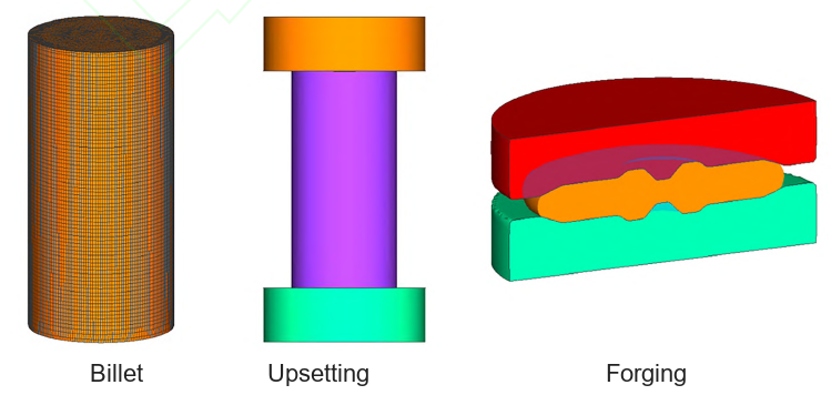
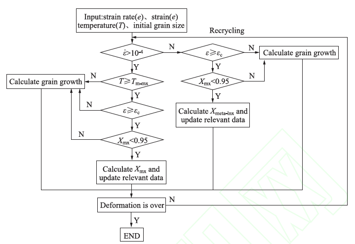
For the critical questions of multi-heat forging, the code was extended by secondary development using a genetic algorithm. In the heating and cooling stages, heat-transfer coefficients calibrated against industrial production data predict the temperature field of bare, canned and semi-canned billets. The microstructure model follows the published GH4169 work of Na et al., with the calculation logic shown in Figure 2; the flow-stress model comes from JmatPro thermodynamic calculation anchored to production data.
Heating and Transfer: Soak-Through Without Cracking a 12 t Billet
The first critical operation is heating — for a supersized billet, a soak-through problem plus a grain-growth problem. Production measures temperature with surface-mounted armored thermocouples, which leave two questions open: the thermocouple reaching temperature does not prove the billet is uniformly heated, and the delay between the two is unknown. Forging an under-soaked billet raises the deformation load, leaves the core poorly recrystallized and hands the disc a non-uniform structure. And after cogging the structure is already inhomogeneous; during reheating every position grows grains according to its own thermal history — the same physics behind austenite grain growth during heating, and a first-order effect on the final grain size.
Figure 3a quantifies the aggressive option: a cold billet charged directly into a 1010 °C furnace for a 30 h hold. When the edge point P3 reaches uniform temperature at 11.5 h, the center point P1 still reads 996 °C — forge then, and the disc is in trouble; P1 only catches up after about 15 h. Worse is the early temperature gap: at 3 h, P1 sits at 268 °C while P3 has already reached 924 °C — a 656 °C difference whose thermal stress can crack the ingot outright.
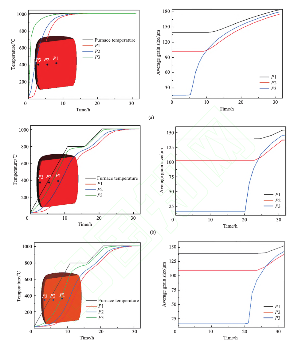
The controlled alternatives are stepped ramps. On a bare billet (Figure 3b) the P1–P3 difference never exceeds 300 °C, with P3 uniform at 25 h and P1 at 29.5 h. With a canned billet under a single-step ramp (Figure 3c), P3 needs 24 h and P1 30 h — a 6 h wait from surface-to-temperature to full uniformity, longer than bare. Grain size tells the same story: after the aggressive direct charge the average grain is distinctly coarser — bad for hot ductility and contrary to the refinement goal — while both stepped schedules hold the billet at 137–152 μm and closely uniform.
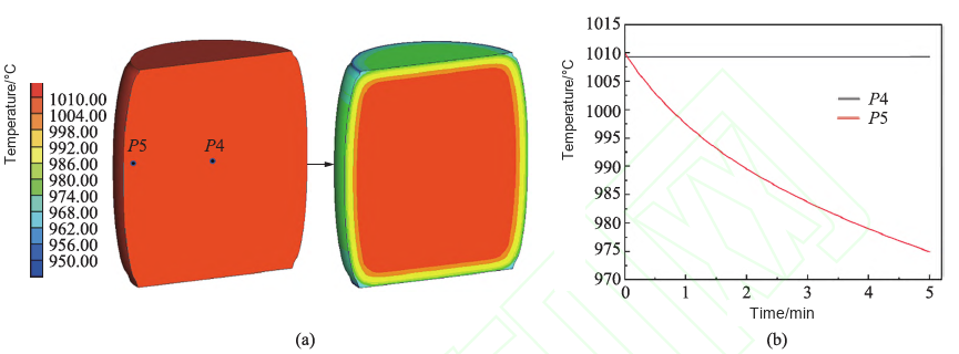
Before forging, the billet is transferred to the hydraulic press. Five minutes in the canned condition costs the edge position P5 a drop from 1010 to 972 °C while the core point P4 barely moves (Figure 4). Ignore transfer heat loss and the simulation will overestimate recrystallization at the edge — so the transfer must be part of the model, not an afterthought.
Hot Deformation: Recrystallization on a Knife Edge
During forging the billet refines its grains by dynamic recrystallization (DRX), and strain rate walks a knife edge. Too fast: DRX drops, the core heats up, and the fresh fine grains grow back coarse. Too slow: the pass takes longer, the edge cools below recrystallization, the dead zone swells and a severe mixed-grain structure forms — the same defect class behind the coarse-grain ring that fails ultrasonic testing in finished bar.
Figure 5 shows the transferred billet upset at 10 mm/s. (a) The core gains about 20 °C while the surfaces touching the flat anvils lose heat heavily. (b) Average grain size comes out in an X-pattern: grade 8–9 at the core, 6–7 spreading outward, 4–5 at the top surface. (c) The DRX fraction peaks at 70% in the core, runs 42–49% through most of the section and falls to 14–28% at the low-strain bulge, with the cold surfaces barely recrystallized. (d) The recrystallized grains sit at 13–16 μm.
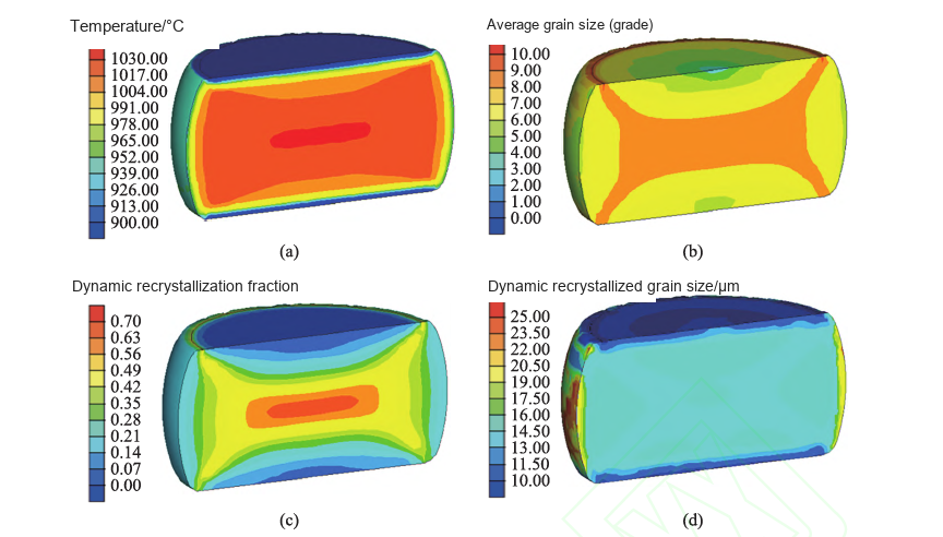
The same framework then explores strain rate, deformation temperature, friction coefficient and die temperature against the microstructure outcome — which is how the process window gets optimized before a single billet is charged.
After the Press: Cooling, Metadynamic Recrystallization and Grain Growth
Once deformation ends, the billet enters metadynamic recrystallization and grain growth. A supersized billet stores enormous heat and sheds it slowly, so the evolution runs long and the structure keeps moving long after the press opens.
Figure 6 tracks it. After 45 s of air cooling, metadynamic recrystallization has already reached 60–70% in places while the billet still sits at 1020–1030 °C. At 6 min 45 s it is complete — and the hot core starts growing, to grade 4–5. From 6 min 45 s to 30 min only growth continues, and the grade 4–5 region keeps widening.
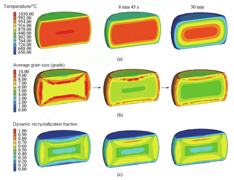
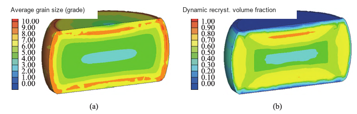
Fully cooled to room temperature (Figure 7), the core ends at grade 3–5 and the edge at 6–8 — refined against the pre-forge state: the pass achieved its purpose. The decisive advantage of the method is what it makes visible: the temperature and structure state of the billet at every instant — data no instrumented production floor could capture — and each pass’s end state (temperature, average grain size) is inherited into the next heat, coupling real production to the model across the whole multi-heat chain.
Press Load: Staying Under the 800 MN Ceiling
Die forging for grain-size control runs at the low end of the hot-working range, where GH4169’s flow stress is brutally sensitive to temperature and strain rate — the natural habitat of “won’t upset”. Predicting the deformation load against the equipment limit is therefore not optional. Figure 8a compares 5 and 10 mm/s at 1010 °C for a 500 mm reduction of the Φ2440 mm disc; Figure 8b compares 1010 and 1030 °C at 5 mm/s. Lower speed and higher temperature both cut the load — but higher temperature also coarsens the grains after deformation. And all four conditions still peak above 900 MN, beyond China’s largest 80,000 t (800 MN) press.
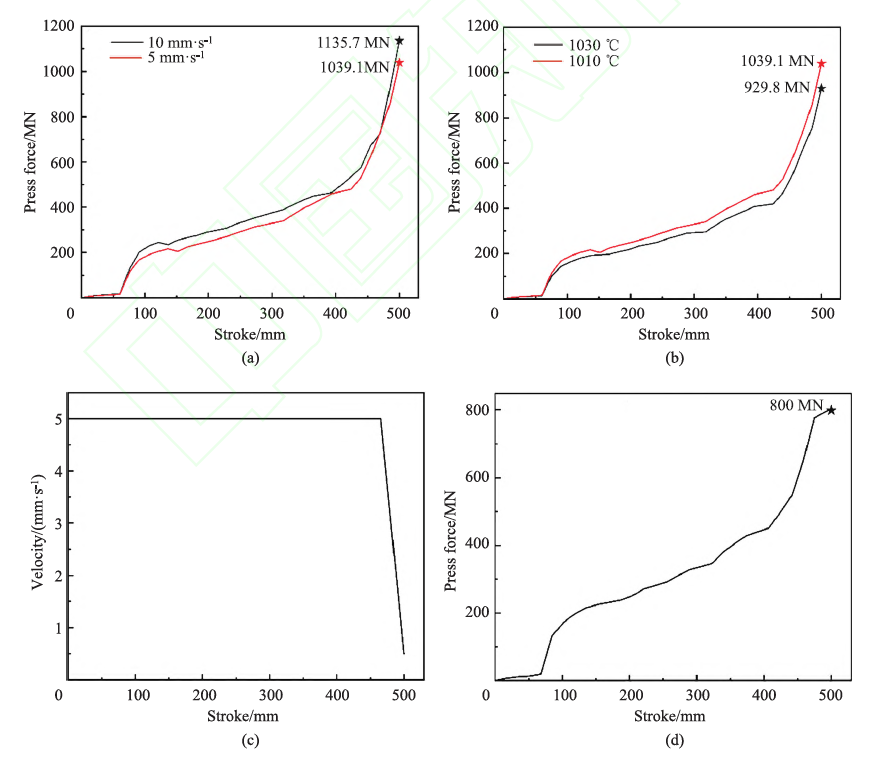
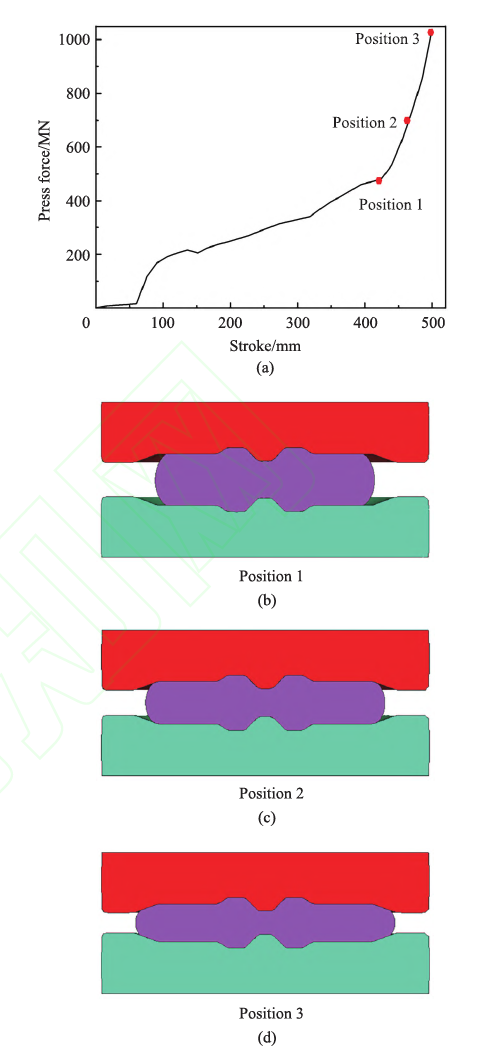
The way out was a non-uniform ram speed (Figure 8c): constant velocity over the first half of the stroke, decelerating over the second. The simulated peak lands at 800 MN (Figure 8d), and the gentler late reduction additionally favors recrystallization inside the billet. The late-stage load surge has a plain mechanical explanation: the metal flows from the end faces sideways until the cavity fills, so the billet–die contact area keeps growing — Figure 9 shows the contact states at Positions 1 to 3 on the load curve; near Position 3 the die wall grips the billet’s side wall, adding compressive stress exactly when the stroke is deepest.
With this method, deformation load can be pre-assessed for any alloy, ingot size and press configuration at the process-design stage — slashing the “won’t upset” risk long before tooling is cut.
Forging the Φ2440 mm Disc — and Proving the Model Right
Combining the full-process analysis with the integrated calculation method, the three-heat forging of the Φ2440 mm GH4169 disc was designed starting from the post-cogging billet state. The result: China’s largest nickel-based superalloy turbine disc, forged successfully under simulation control (Figure 10).
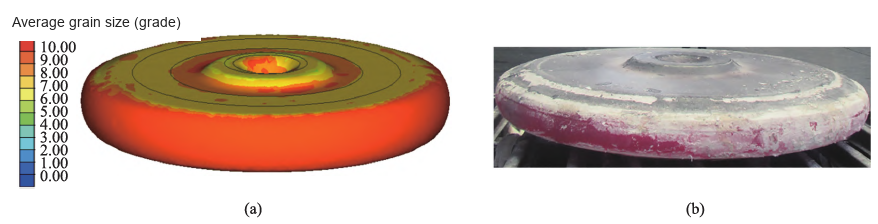
Validation came the hard way — longitudinal dissection and metallography. Specimens were ground, polished, grain-boundary etched in boiling 2.5 g KMnO₄ + 10 mL H₂SO₄ + 90 mL H₂O for 4–6 min, dipped for 5–8 s in boiling supersaturated oxalic acid, ultrasonically cleaned in ethanol and examined under an optical microscope. Table 1 sets the measured grain-size grades against the simulation:
| Position on the disc section | Measured average grain size (grade) | Simulated average grain size (grade) |
|---|---|---|
| A1 | 9.0 | 8.6 |
| A2 | 8.5 | 8.2 |
| A3 | 8.5 | 8.2 |
| A4 | 8.5 | 9.0 |
| A5 | Within 0.3 grade of simulation | — |
Table 1 — Measured vs simulated average grain size at five dissected positions: every position agrees within 0.5 grade.
Every position agrees within half a grade — the model is validated for both accuracy and reliability.
Key Takeaways for Buyers and Engineers
For anyone specifying or buying supersized superalloy forgings, the case distills into a short list:
- Ask how grain size is engineered, not just inspected. Uniform grain size across a Φ2440 mm disc came from schedule design — stepped and canned heating ramps, strain-rate control, managed cooling — not luck. Grain size is also what ultrasonic testing sees, which is worth understanding before writing acceptance criteria (see how ultrasonic inspection works).
- Multi-pass coupling is the hard part. Temperature and microstructure must carry over from heat to heat; a model that resets each pass misses exactly the risks that matter on a disc this size.
- Press capacity is a design input. Load simulation against the press ceiling — and countermeasures such as non-uniform ram speed — belong in process design, not in the post-mortem.
- Simulation data is production data. The temperature and structure states visualized at every instant are unobtainable by instrumentation at this scale, and they are what make grain-size requirements negotiable and deliverable.
| Process stage | Dominant risk | Model-based control |
|---|---|---|
| Heating | No soak-through; thermal-stress cracking; runaway grain growth | Stepped / canned ramp schedules; quantified soak times; P1–P3 difference held under 300 °C |
| Transfer | Edge heat loss on the way to the press | 5-min canned transfer quantified: edge 1010 → 972 °C, core unchanged |
| Hot deformation | Coarse grain (too fast) or mixed grain (too slow) | Strain-rate / temperature window chosen from DRX fraction and grain-size fields |
| Cooling | Metadynamic recrystallization plus grain growth | Grain size predicted along the cooling path to room temperature; states inherited pass to pass |
| Die forging | Load beyond the press limit — “won’t upset” | Non-uniform ram speed holds the peak at 800 MN; late-stage surge explained by contact-area growth |
Table 2 — Risk points and model-based controls across the GH4169 disc forging chain.
FUSHUN METAL supplies nickel-based superalloys — Inconel 718 / GH4169 bar, forgings and discs among them — through the full product range, and approaches forgings the way this disc was forged: melt route, forging schedule, grain-size control and heat treatment decided as one engineering problem. If your application calls for GH4169 or another superalloy forging, send us the grade, size, standard and service conditions, and we will come back with a workable supply route and the supporting documentation.