Surface cracks were visually discovered on wire-cut samples taken from the platform section of aluminum alloy forgings. Metallographic inspection attributed the cracking to excessive residual stress during the cutting process and grain boundary weakening caused by second-phase precipitation. To confirm whether similar defects exist in other forgings, lateral wave ultrasonic testing was applied. Suspected crack-like indications were further verified using X-ray, dual-crystal longitudinal wave, and penetrant testing, which ultimately ruled them out as true defects.
Background of the Issue
Initial Discovery
During routine performance testing, a 15 cm crack was found on the side surface of a sample taken from the forging’s platform area using wire cutting. The crack formed at approximately a 45° angle with the platform face. Another suspected fold-type defect, visible on the surface and through the entire thickness, was also discovered.
Metallographic analysis confirmed the failure as stress-induced cracking. No inclusions or metallurgical defects were present on the crack face. The grains were relatively fine, and second-phase particles were observed precipitating along grain boundaries. The conclusion: cracking occurred during wire cutting due to excessive residual stress, with the second-phase weakening the grain boundaries contributing secondarily.
Preliminary Ultrasonic Testing
Technicians used a 5P14 straight probe to test from the platform’s end face. Due to too many reflective sources in the longitudinal wave mode, defects could not be confirmed. Given the perpendicular orientation of the crack relative to the surface, the team referred to GB/T 7233.1—2009 and applied lateral wave detection. Using a 4P8×8 60° FG15 dual-crystal shear wave probe, a 40 mm long, 17.4 mm deep strip-shaped indication was found, potentially a crack.
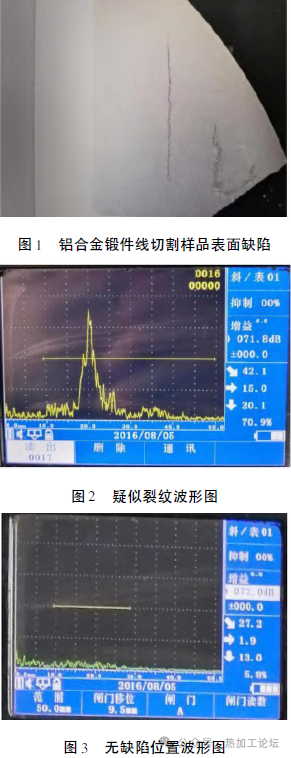
1. Metallographic image showing grain boundary cracking and second-phase precipitation in aluminum alloy forging. 2. Lateral wave echo image showing strip-shaped indication in aluminum forging. 3. Comparison waveform from non-defective aluminum forging section.
Validation Methods for Suspected Cracks in Aluminum Forgings
Since only one forging showed the suspected defect, additional validation was essential. The following three methods were used:
1. X-ray Inspection
The ultrasonic indication was marked, and the echo length was measured using the echo-loss method. Probe movement perpendicular to the indication revealed no parallel defects or angled planar reflections. The defect’s shape was inferred as elongated rather than planar. X-rays were used to confirm, taking advantage of their effectiveness in detecting perpendicular or volumetric flaws.
2. Penetrant Testing
After localization via lateral wave, the suspected region was wire-cut and subjected to dye penetrant inspection. This surface-only NDT method relies on capillary action. If the indication was a real crack, cutting perpendicular to its length would expose it, and the dye would reveal its cross-section.
3. Longitudinal Wave Detection
Dual-crystal longitudinal probes were used to examine areas parallel to the indication. While noise is common in straight-probe detection, already knowing the echo’s location helped focus inspection. If reflections at the same depth and direction were seen, a crack could be confirmed. If not, and the echo angle differed, additional small-angle or lateral probes were applied.
Experimental Verification
3.1 X-Ray Testing
3.1.1 X-Ray Principles
When X-rays pass through materials, their intensity is reduced due to scattering and absorption. The attenuation depends on the material’s thickness and attenuation coefficient. If a flaw is present, it alters the transmitted intensity. A photographic film placed behind the object captures this variance as different shades, revealing defect locations.
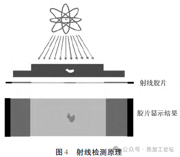
X-ray principle diagram showing defect detection via transmitted intensity on film.
The key component of radiographic film is silver halide, which turns black when exposed to light. Higher exposure leads to darker film, creating contrast for defect imaging. Radiographic sensitivity is defined by detectable wall thickness percentage differences—typically, 2% is sufficient for industrial needs.
3.1.2 X-Ray Parameters
- Device: XP450 MXR451/26 X-ray system
- Focal spot size: 5.5 mm
- Film: AGFA C7
- Screens: Front 0.03 mm, rear 0.1 mm lead foil
- Back protection lead plate: 2 mm
- Exposure setup: Longitudinal seam, single-wall view (see 图5)
- Voltage: 70 kV
- Exposure: 30 mA·min
- Film development: Manual
- Developing temp/time: 20°C, 5 min
- Fixing time: 15 min
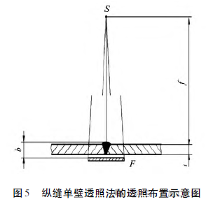
Diagram of single-wall X-ray exposure setup for aluminum forging inspection.
3.1.3 X-Ray Results
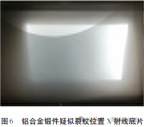
Radiographic film showing no detectable flaws in the inspected forging.
No defects were found in the radiographic images.
3.2 Contact-Type Longitudinal Dual-Crystal Probe Testing
3.2.1 Inspection Status
After X-ray inspection, wire cutting was performed perpendicular to the suspected indication. The sample was divided into three parts (labeled #1, #2, #3).
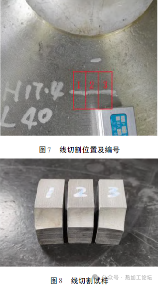
Diagram of sample cut locations from the forging platform. 8. Photo of three cut samples used for ultrasonic verification.
3.2.2 Ultrasonic Testing Parameters
- Device: USM86 Digital Ultrasonic Flaw Detector
- Probe: 5MHz, 4×12FG15M dual-crystal longitudinal
- Calibration block: Aluminum step block with ø2 mm flat-bottom holes
Sensitivity: 40% echo amplitude at maximum depth - Scanning direction: Perpendicular to the suspected crack face
3.2.3 Results
All three samples showed no defect echoes.
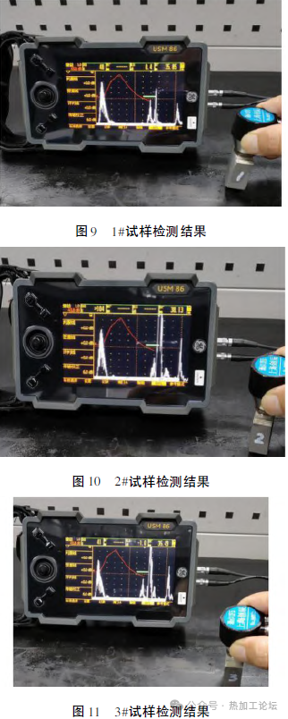
9 & 11: Ultrasonic B-scan images of samples #1, #2, and #3 showing no defect indication.
3.3 Penetrant Testing
3.3.1 Principle
Penetrant testing uses dyes and capillary action to highlight surface-breaking defects. After applying the dye, the part is cleaned and dried. A developer is then applied to draw dye from cracks. The fluorescent or colored residue reveals flawed geometry under light.
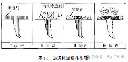
Flowchart of the penetrant testing process for surface crack detection.
3.3.2 Parameters
- System: Level 2 sensitivity dye penetrant (GB/T 18851.2—2008 compliant)
- Reference block: Type 2, GB/T 18851.3—2008
- Temperature: 30°C
- Penetrant time: 10 min
- Rinse: Water wash
- Develop time: 10 min
- Result: 5 clear dots on reference block
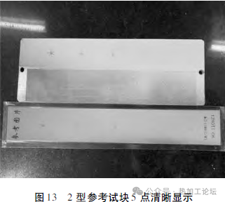
Reference block showing clear indications during penetrant testing.
3.3.3 Results
No defects were found on all three samples.
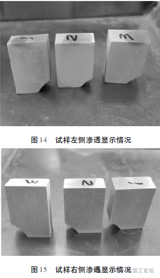
14 & 16. Penetrant test images of samples #1, #2, and #3 show no surface cracks.
3.4 Summary of Validation
The combined use of X-ray testing, dual-crystal longitudinal wave ultrasonic inspection, and penetrant testing found no actual cracks in the regions identified by lateral wave testing. The original lateral wave echoes were confirmed to be false positives.
Conclusion
The GB/T 7233.1—2009 standard includes a method for using diffracted echoes at both ends of a defect to determine flaw size in the thickness direction. While highly sensitive and not requiring test blocks, this method must be applied cautiously to avoid misinterpreting echoes as defects, especially in aluminum alloy forgings.
When lateral wave echoes resembling cracks are detected, it is essential to validate them using complementary NDT techniques. Validation should consider defect shape, depth, and orientation provided by ultrasonic data, and may include:
- X-ray inspection
- Straight or small-angle probe ultrasonic testing
- Metallographic sectioning (if permissible)
Only if a secondary method confirms a flaw at the same location should it be treated as a true strip-shaped defect.