
Steel Microstructure: The Six Structures That Decide Hardness and Toughness
Two bars of the same 45 steel, same heat number, same certificate. One machines cleanly at 200 m/min; the other destroys the insert on the first pass. Nothing in the chemical analysis explains it. What changed is the microstructure — and once you can read the six basic structures, you can predict what a heat treatment will do before the furnace is switched on.
Why the same grade behaves like two different materials
Take 45 steel — GB/T 699, close to AISI 1045, 0.45 % carbon. Annealed, it sits at about 180 HB and a carbide tool walks through it. Quenched and untempered, the same bar reaches 55 HRC and a file skates off it. Chemistry identical, hardness tripled.
The explanation is that hardness in steel is not a property of the composition. It is a property of the arrangement — which phases are present, in what shape, at what size, and how much carbon is still dissolved in the iron instead of sitting in a carbide. Change the arrangement and you change the metal, without touching the alloy.
There are six structures worth knowing. Five of them you will meet on a drawing or a purchase order; the sixth is the one you never want to find in a finished part.
Allotropy: iron changes its own crystal structure
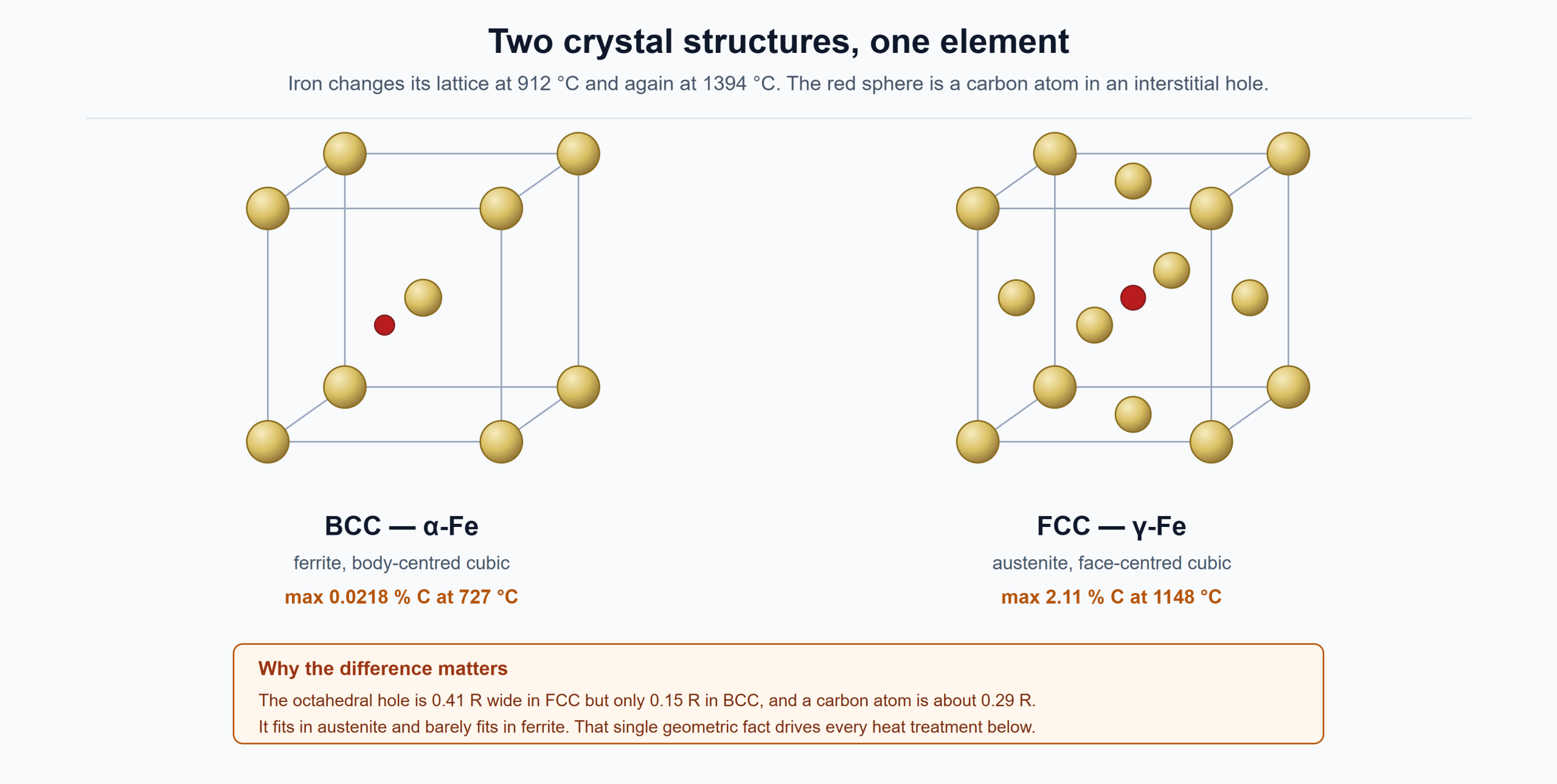
Before the structures themselves, one fact that explains all of them. Pure iron does not keep one crystal lattice at every temperature. At room temperature it is body-centred cubic, α-Fe. Above 912 °C it rearranges into face-centred cubic, γ-Fe. Above 1394 °C it goes back to body-centred cubic as δ-Fe, and melts at 1538 °C.
The two lattices hold carbon very differently. The octahedral hole in the face-centred cell is about 0.41 R across; in the body-centred cell it is 0.15 R, and it is not even symmetric. A carbon atom is roughly 0.29 R. So carbon fits into γ-Fe almost comfortably and into α-Fe only by forcing the lattice apart:
- α-Fe (BCC) dissolves a maximum of 0.0218 % carbon, at 727 °C. At room temperature the figure is closer to 0.00005 %.
- γ-Fe (FCC) dissolves a maximum of 2.11 % carbon, at 1148 °C. At 727 °C it still holds 0.77 %.
A hundredfold difference in solubility, in the same element, caused by a change of packing. That gap is the entire basis of heat treatment: dissolve carbon in γ at high temperature, then cool fast enough that it cannot get out, and you have made a structure that is supersaturated and hard. Slow down and the carbon leaves as carbide, and you get a soft structure instead.
The map every heat treatment follows
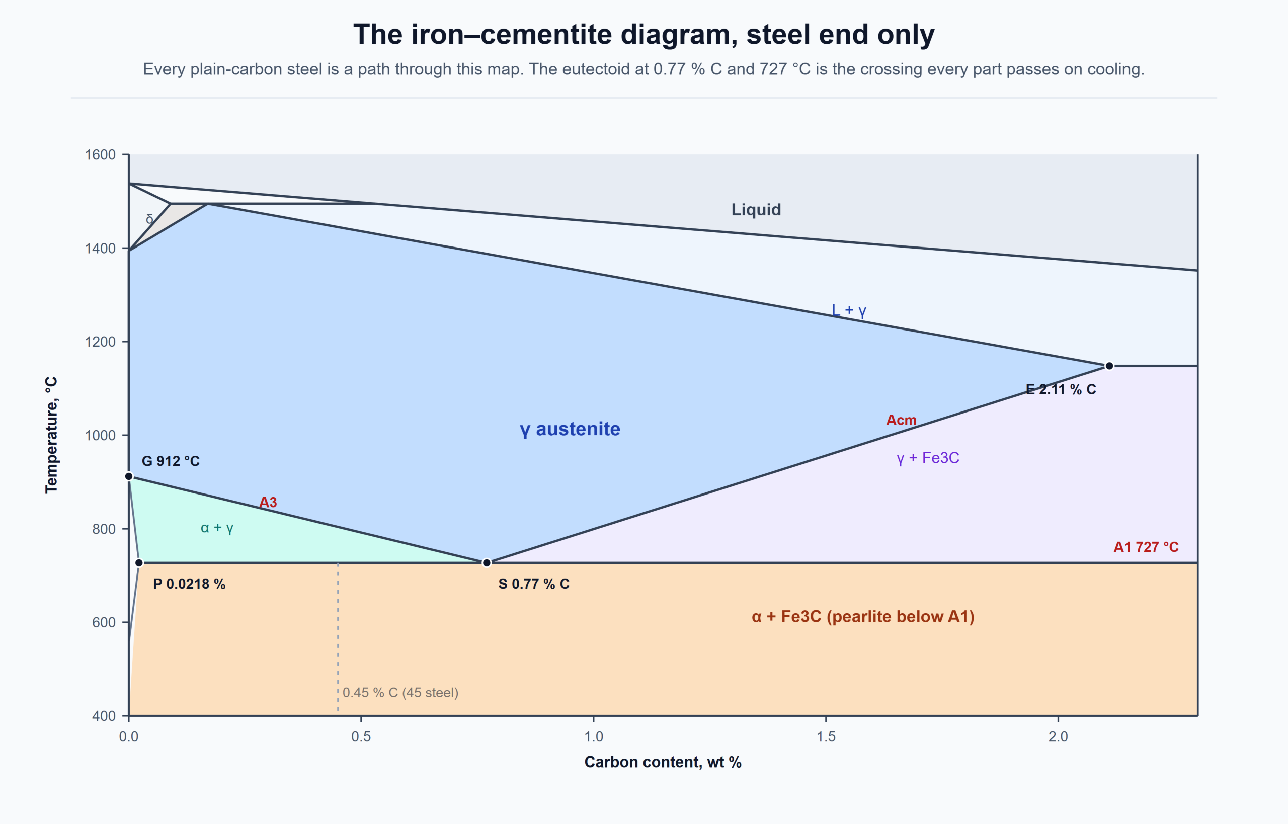
The iron–cementite diagram is the working map. For plain-carbon steels only three features of it matter most of the time:
- A1, 727 °C — the eutectoid temperature. Every steel crosses it on cooling, and what happens there decides the room-temperature structure.
- S, 0.77 % C — the eutectoid composition. At this carbon content, austenite transforms into pearlite in a single reaction, with no free ferrite and no free cementite.
- E, 2.11 % C — the limit of carbon in austenite. Above it, the leftover carbon appears as primary cementite, which is why cast irons behave nothing like steels.
Below 0.77 % C a steel is hypoeutectoid: on slow cooling, ferrite forms first along the austenite grain boundaries, and the remaining austenite reaches 0.77 % and becomes pearlite. Above 0.77 % it is hypereutectoid: cementite forms first, as a network on the boundaries, and the core becomes pearlite. That network is why a 1.0 % C bearing steel is bought spheroidise-annealed, not normalised.
Ferrite: soft, ductile, and the reason low-carbon steel welds
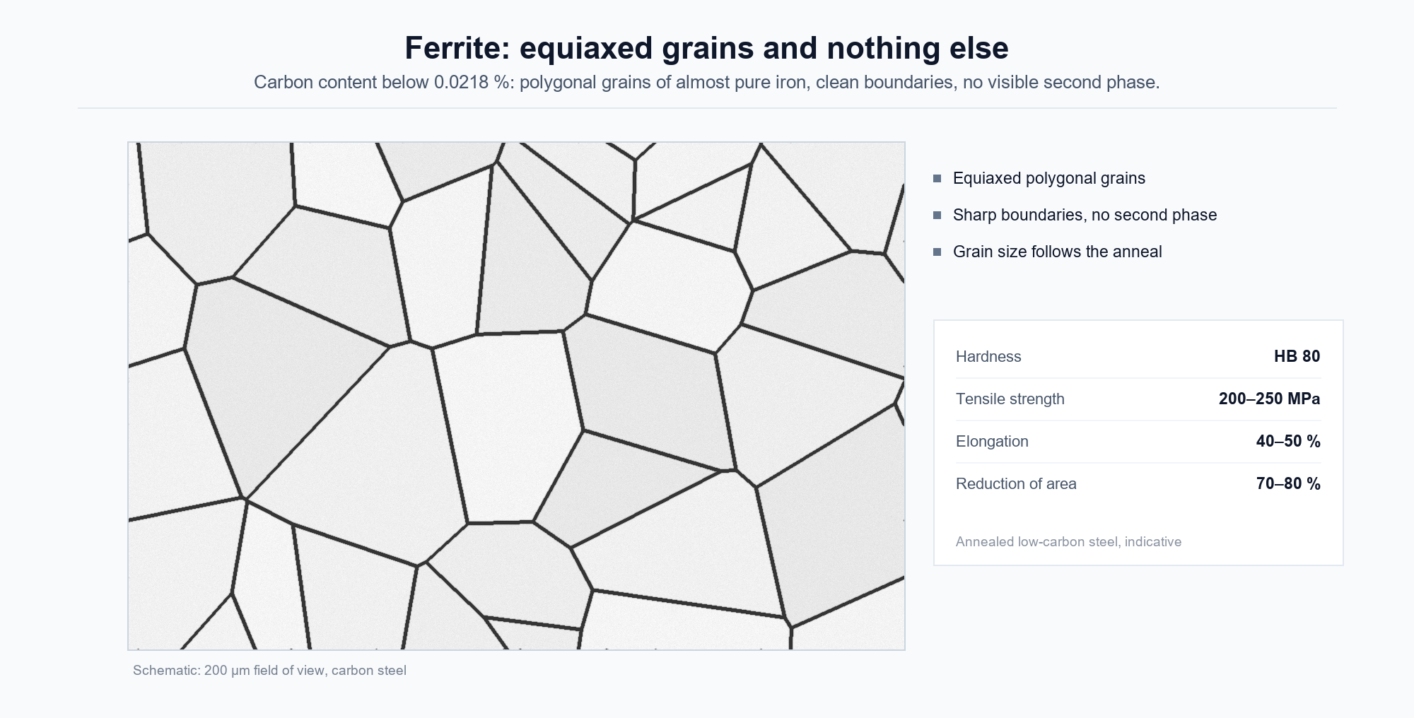
Ferrite is carbon dissolved in α-Fe — an interstitial solid solution, symbol F. Because the lattice holds so little carbon, ferrite is effectively pure iron with a few atoms of carbon wedged into it, and its properties are the properties of pure iron: low strength, low hardness, excellent ductility.
Under the microscope it appears as white, equiaxed polygonal grains with clean boundaries and nothing inside them. If you can see a second phase in the field, it is not ferrite.
Typical values: HB 80, tensile strength 200–250 MPa, elongation 40–50 %, reduction of area 70–80 %. It deforms a long way before it breaks — which is exactly what a deep-drawn sheet, a bent tube or a welded fabrication needs.
Low-carbon steel below 0.25 % C is ferrite plus a little pearlite. Annealed, it is soft enough to blank, form and weld without cracking; that is why structural plate, welded pipe and cold-formed sections are all made from it. The same softness is a liability the moment somebody specifies a wear surface.
One practical consequence worth knowing: free ferrite in a quenched part is a soft spot. If a 0.4 % C bar comes back from hardening at 45 HRC in one zone and 25 HRC in another, the low reading is usually ferrite that never dissolved — either the austenitising temperature was short of A3, or the section was too thick to cool through.
Austenite: the high-temperature structure everything starts from
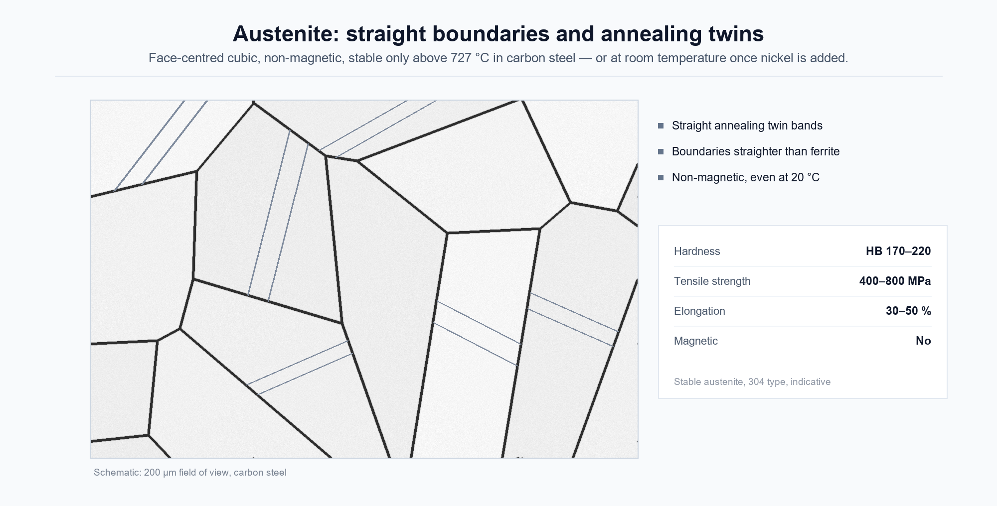
Austenite is carbon dissolved in γ-Fe, symbol A. It holds up to 2.11 % C, it is non-magnetic, and in carbon and low-alloy steels it exists only above 727 °C. Under the microscope its grains are equiaxed but the boundaries are straighter than ferrite’s, and many grains carry straight parallel bands — annealing twins, a stacking fault in the FCC lattice and a reliable fingerprint for the structure.
Austenite is not usually a product. It is the starting condition. Every hardening, normalising and annealing cycle begins by heating into the austenite field, because that is the only way to dissolve the carbides and redistribute carbon. Hot rolling and forging are done in the same state, for a simpler reason: FCC iron has more slip systems, so it deforms without cracking.
Two things about austenite cause most of the trouble in a heat-treat shop:
- Grain growth. Hold austenite too hot or too long and the grains coarsen. Coarse grains mean coarse martensite, more distortion, and a lower impact energy. Aluminium-killed fine-grain steels resist this up to about 1000 °C; beyond that, nothing helps.
- Retained austenite. In high-carbon steels the martensite finish temperature sits below room temperature, so 10–20 % of the austenite never transforms. It is soft, it is unstable, and it turns into martensite later — after grinding, or in service — changing the dimensions of a finished part. That is why 1.0 % C bearing and die steels get a sub-zero or double temper treatment.
The exception is the austenitic stainless family. Add enough nickel and manganese — 8 % Ni and 18 % Cr in 304, for example — and austenite stays stable all the way down to room temperature. That is why 304 and 316 are non-magnetic, why they cannot be hardened by quenching, and why they work-harden instead.
Cementite: hard, brittle, and useful only in company
Cementite, Fe3C, is not a solid solution. It is an intermetallic compound with a fixed composition of 6.69 % C and its own orthorhombic crystal structure. It is hard — above HB 800, harder than most hardened steel — and it has essentially no ductility. A piece of cementite would shatter if you dropped it.
For that reason it never appears alone. Its engineering value lies entirely in its shape, size and distribution:
- Lamellar (the plates inside pearlite) — the strongest strengthening form, at the cost of ductility and machinability.
- Spheroidised (globules in a ferrite matrix) — less strengthening, but the softest, most machinable condition a high-carbon steel can be in. This is the standard supply condition for D2, 52100 and most cold-work die steels.
- Network (a film along the grain boundaries) — the one you reject. A continuous carbide network gives a brittle path through the steel and is a standard item on the inspection sheet for bearing and tool steels.
That is why a high-carbon tool steel is bought spheroidise annealed rather than annealed: the specification is not just a hardness number, it is a carbide shape. See our note on spheroidising D2 and the austenitising temperature that follows for how the two steps interact.
Pearlite: two phases, one lamella at a time
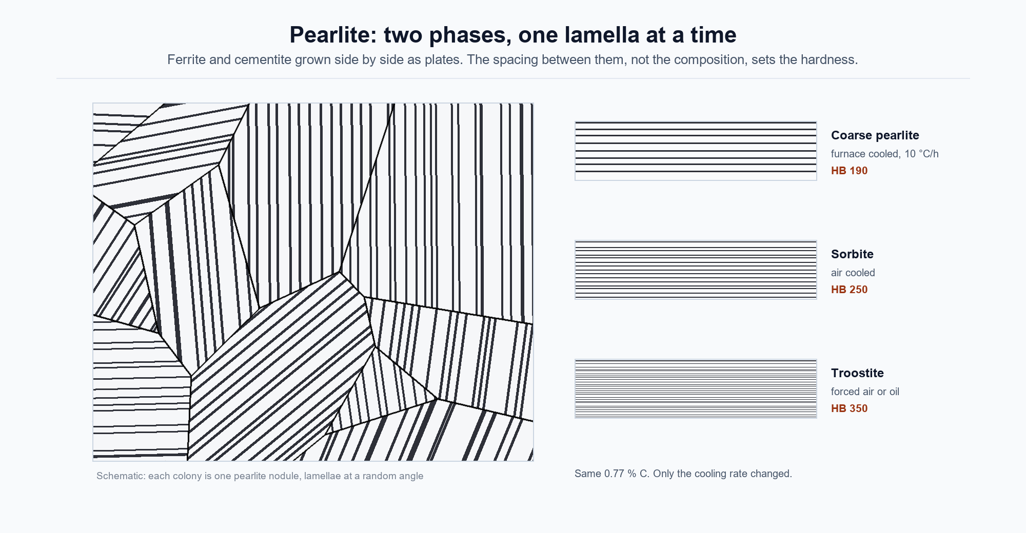
Pearlite, symbol P, is what austenite of eutectoid composition becomes when it is cooled slowly: ferrite and cementite growing side by side as alternating plates. At 0.77 % C the mix works out to roughly 88 % ferrite and 12 % cementite by mass.
The morphology is distinctive. Plates form in colonies — nodules — and within each colony all the plates share one orientation, so a micrograph at low magnification looks like a patchwork of differently striped regions. At high magnification the stripes resolve into the two phases.
Its properties sit between the two constituents: harder than ferrite, tougher than cementite. HB 180–250, tensile strength 600–800 MPa, elongation 10–20 %.
The variable that matters is the spacing between the plates, and spacing is set by the temperature at which the transformation happens — which is set by the cooling rate. Faster cooling pushes the transformation to a lower temperature, the carbon cannot diffuse as far, and the plates get finer:
- Coarse pearlite, spacing above 0.5 µm, furnace cooled. HB 190 or so. The softest, most machinable pearlitic condition — what full annealing is for.
- Sorbite, around 0.3 µm, air cooled or normalised. HB 250–320 with better strength at the same ductility. Normalising a medium-carbon steel is a way of getting sorbite on purpose.
- Troostite, below 0.3 µm, forced air or oil. HB 330–400. The name is old-fashioned but still used on Chinese mill certificates.
All three are pearlite. Same phases, same composition, different fineness — and a spread of nearly 200 HB. It is the clearest illustration in metallurgy that structure, not composition, sets properties.
Pearlite also has one high-volume application that is easy to miss: patenting of wire rod. A eutectoid steel is heated to austenite and then passed through a lead or fluidised bed at about 500 °C, producing a very fine pearlite that draws down to 0.2 mm without breaking. Coarse pearlite cannot do that.
Martensite: the structure you make on purpose and then modify
Martensite, symbol M, is carbon trapped in α-Fe at a concentration the lattice cannot hold — a supersaturated solid solution. It forms without diffusion. The austenite does not decompose; the whole lattice shears into a new shape in a fraction of a second, carrying its carbon with it.
Because no atoms move, the transformation is not a matter of time but of temperature. It begins at Ms and finishes at Mf, both of which fall as the carbon content rises — roughly 350 °C at 0.45 % C, roughly 220 °C at 0.8 % C. Anything that stops the part above Mf leaves austenite behind.
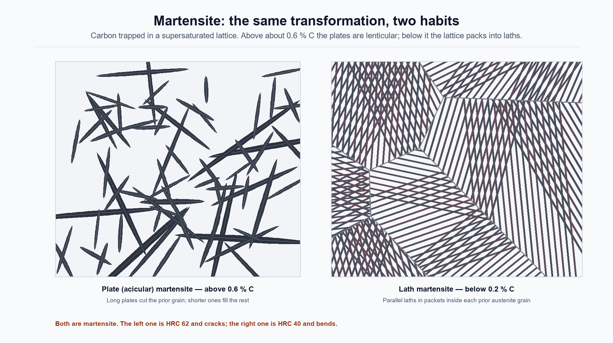
The habit changes with carbon. Above about 0.6 % C the plates are lenticular: long, sharp, crossing each other at angles, with a visible midrib. Below about 0.2 % C the structure is lath martensite instead — bundles of parallel laths, each bundle a packet, filling the prior austenite grain.
The two behave very differently:
- Plate martensite, high carbon: HRC 62–66, very brittle, high internal stress, and microcracks at the plate tips. It cannot be used as-quenched; it must be tempered immediately, and often it cracks during the quench anyway.
- Lath martensite, low carbon: HRC 38–45, with a strength-to-toughness balance that is good enough to use with little or no tempering. This is why low-carbon martensitic steels and Q&T plate steels have displaced conventional normalized grades.
One number explains the distortion: martensite occupies about 4 % more volume than the austenite it came from. A part that transforms unevenly — thin section before thick, surface before core — has to accommodate that expansion somewhere. It either bends or it cracks. Slow the cooling, equalise the section, or use a marquench, and the same structure arrives with less stress.
As-quenched martensite is never the finish condition. Tempering heats it to 150–650 °C, lets the carbon precipitate as fine carbide, and produces tempered martensite, tempered troostite or tempered sorbite depending on temperature. Hardness falls, toughness rises, stress is relieved. If you want the underlying mechanism, we have written separately about what quenching does and what it does not.
Bainite: the structure between the nose and Ms
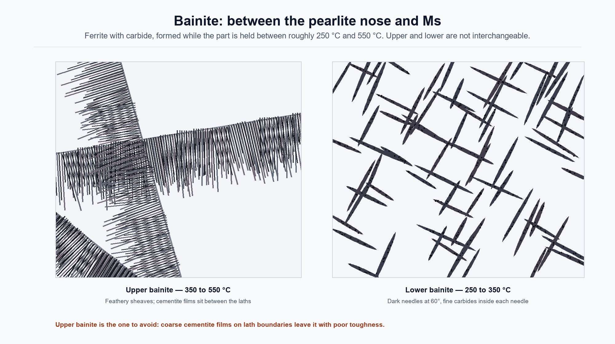
Cool too fast for pearlite and too slowly to miss the C-curve, and you land in the bainite bay. Bainite is ferrite with carbide, but unlike pearlite the carbide is not in neat plates; it is distributed inside or between ferrite laths, depending on the temperature.
The temperature divides it into two structures with almost nothing in common:
- Upper bainite, 350–550 °C. Feathery sheaves grown from the austenite grain boundaries, with cementite films lying between the laths. The films are continuous, so the toughness is poor — often worse than coarse pearlite at the same hardness. It is a structure to avoid.
- Lower bainite, 250–350 °C. Dark needles crossing at about 60°, with fine carbides precipitated inside each needle. Strength close to tempered martensite, toughness better than it, and — the practical advantage — far less distortion.
The process that produces lower bainite deliberately is austempering: quench into a salt bath or fluidised bed held at 250–350 °C, equalise, hold until the austenite has transformed, then cool in air. Because the part is at a uniform temperature throughout the hold, there is no thermal gradient and no transformation gradient, so the distortion is a fraction of what a conventional quench produces. Springs, gears, die inserts and thin-section parts that cannot be straightened afterwards are the usual candidates.
The limit is hardenability. The hold only works if the section is thin enough to reach the bath temperature quickly and if the steel will transform to bainite rather than pearlite during the hold. That is a question about the steel, not the process — the same question hardenability and the critical cooling rate answer for quenching.
How the cooling curve chooses for you
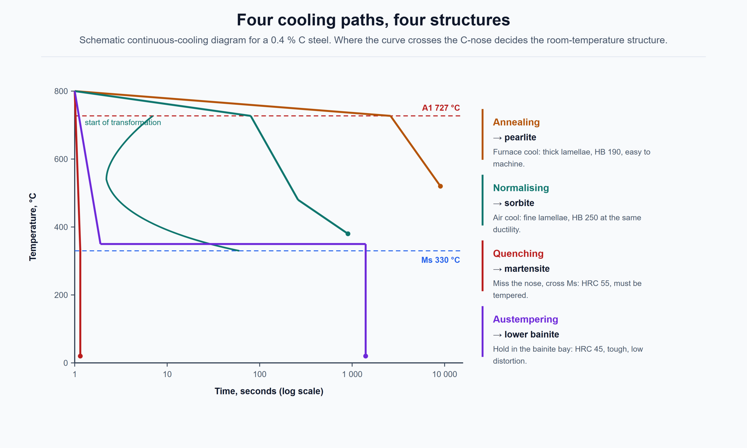
Put the six structures on one temperature–time chart and the whole subject collapses into a single question: where does the cooling curve cross the transformation curve?
- Cross it slowly, at high temperature → pearlite.
- Cross it faster, still above about 500 °C → sorbite.
- Miss it entirely and cross Ms → martensite.
- Stop in the bay between 250 and 350 °C and wait → lower bainite.
This is why the same steel can be sold in four different conditions and why the cooling medium matters more than the austenitising temperature for the final result. It is also why section size matters: a 25 mm bar and a 250 mm forging cannot follow the same curve, however good the furnace is. A centre that cools at one tenth the surface rate will not be martensite, and no amount of tempering will make it uniform.
One table to compare them
Use this as a reading key rather than a specification. Values are indicative for plain-carbon and low-alloy steels; alloying moves them, and so does section size.
Table 1. The six basic structures side by side. Hardness and elongation are indicative ranges, not acceptance limits.
| Structure | What it is | Under the microscope | Hardness | Elongation | Where you meet it |
|---|---|---|---|---|---|
| Ferrite (F) | C in α-Fe, max 0.0218 % | White equiaxed grains, clean boundaries | HB 80 | 40–50 % | Sheet, welded parts |
| Austenite (A) | C in γ-Fe, max 2.11 % | Equiaxed, straight boundaries, twins | HB 170–220 | 30–50 % | Hot working only |
| Cementite (Fe3C) | Intermetallic, 6.69 % C | Plates, globules or a boundary network | HB 800+ | ~0 | Inside pearlite |
| Pearlite (P) | Ferrite + cementite lamellae, 0.77 % C | Striped colonies, plates at one angle | HB 180–250 | 10–20 % | Annealed bar |
| Martensite (M) | Supersaturated C in α-Fe | Needles, or packets of parallel laths | HRC 40–66 | 1–12 % | Q&T parts |
| Bainite (B) | Ferrite with fine carbide | Feathery sheaves, or needles at 60° | HRC 40–50 | 10–15 % | Austempered parts |
Where each one sits on the hardness–ductility map
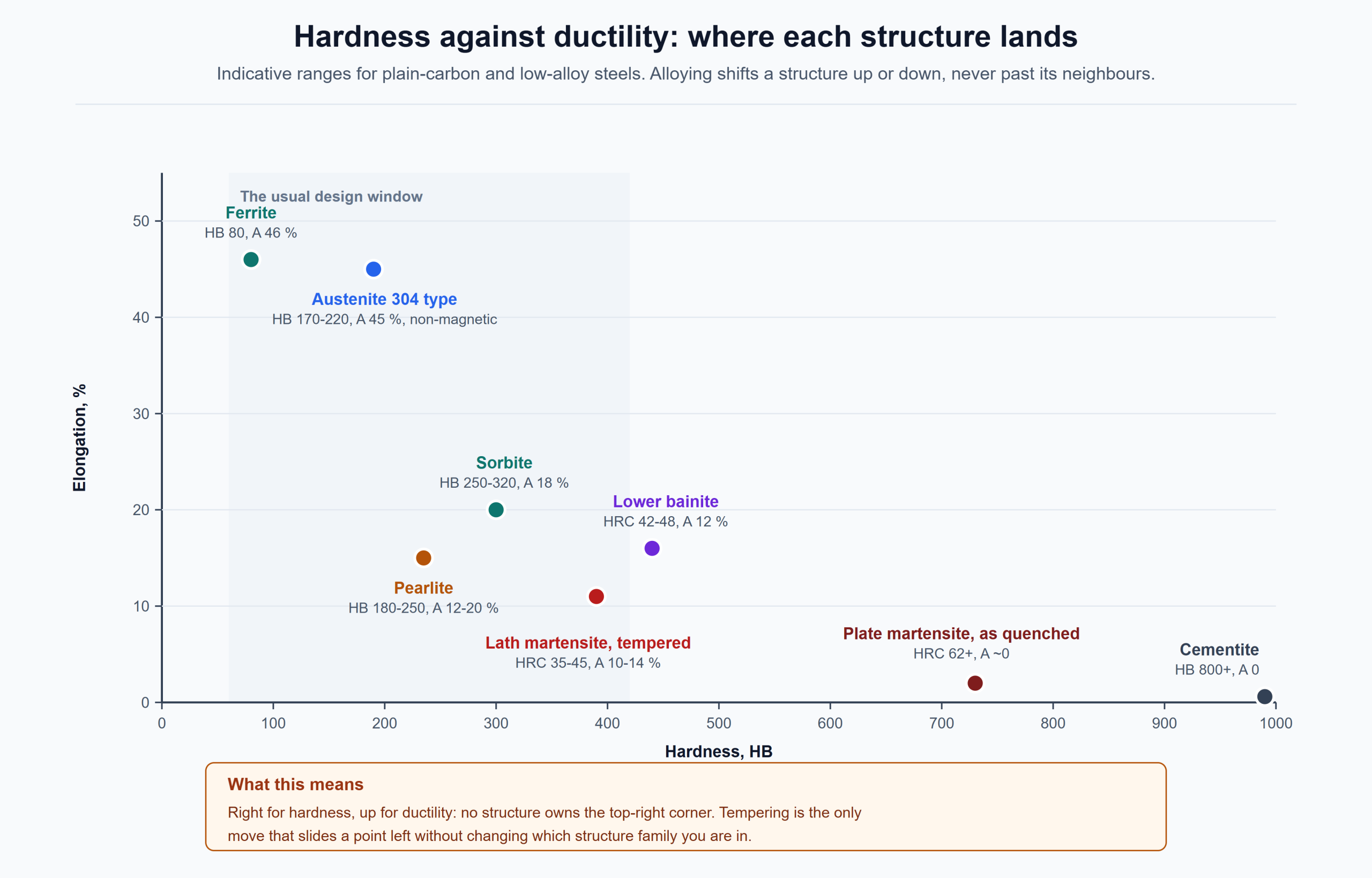
No structure is better than another in the abstract; they occupy different corners of one trade-off. Read the chart rightwards for hardness and upwards for ductility, and note that nothing occupies the top right corner — that corner does not exist in steel.
What to write on the purchase order
Most microstructure arguments start because the order said “heat treated” and both sides assumed something different. These are the five conditions worth spelling out:
- Annealed, maximum hardness. “Full annealed to 170–210 HB” is a machining instruction: coarse pearlite, free of bainite and martensite. Fine for a part that will be cut, not for one that will be used.
- Spheroidise annealed, with a carbide size. The right call for D2, 52100 and other high-carbon grades. Hardness alone is not enough — add the carbide size or a micrograph requirement, or you can receive a hard, unmachinable structure that still passes the hardness test.
- Normalised. Air cooled, sorbite, better strength than annealed at acceptable machinability. Common on forged bars and blanks before finish machining.
- Quenched and tempered, with a hardness range. “Q&T to 28–32 HRC” fixes the tempering temperature but says nothing about whether the core hardened. For sections above about 60 mm, add a hardenability requirement or a core property.
- Austenitising condition for a part you will heat treat yourself. If you machine then harden in-house, buy annealed or spheroidise annealed and specify the structure, not the final hardness.
If you are choosing between grades for a part where the heat treatment is still open, send the drawing and the required properties rather than the grade name. In most cases the grade follows from the structure you need — not the other way round.
Related reading
- Steel heat treatment: six questions from annealing to hardenability — the cycle that produces each structure, and how to choose one
- What is quenching? — cooling media, cooling rates and what each one can and cannot harden
- AISI D2 / 1.2379 / SKD11 spheroidising — why a 60 °C drop in austenitising temperature changes the carbide
- Metallography: stopping the over-etch — how to prepare a specimen that actually shows the structure you are arguing about
You get chemical composition, mechanical properties and a price — with inspection certificates to EN 10204 3.1 issued against the heat number.