
Control Forging of Nuclear Forgings: Grain Size Is the Real Specification
Two upper-flange rings, same grade, same drawing, same ultrasonic acceptance. One Charpy set lands at 180 J on the upper shelf; the other at 90 J. Nothing in the geometry explains it, and nothing in the certificate does either — because both passed. What separated them was how much work the press did in the corner of the ring where the coupon is cut. That corner is where a nuclear forging is actually bought or lost.
A pressure vessel is a forging problem before it is a welding problem
A reactor pressure vessel is a thick-walled pressure boundary that holds the coolant at about 155 bar and 290 °C while the core irradiates it from the inside. It has to be strong at temperature, tough at ambient, weldable, and resistant to neutron embrittlement for forty years of design life — and it has to be all of those things in sections up to 300 mm thick.
Early nuclear islands were largely welded plate structures. As melting, forging and heat treatment control improved, the industry moved to single-piece forgings for the primary boundary, and the reason is straightforward: every weld in a thick section is a place where toughness is lower, inspection is less certain and irradiation damage accumulates differently.
The cost of that move is that the forging starts far from the finished shape. A reactor pressure vessel blank is commonly three times the finished part weight or more, because the discard has to cover the ingot ends, the segregation-rich core and every surface that has been exposed to the furnace atmosphere. That is not waste in the ordinary sense; it is the price of getting a section whose properties are uniform through the wall.
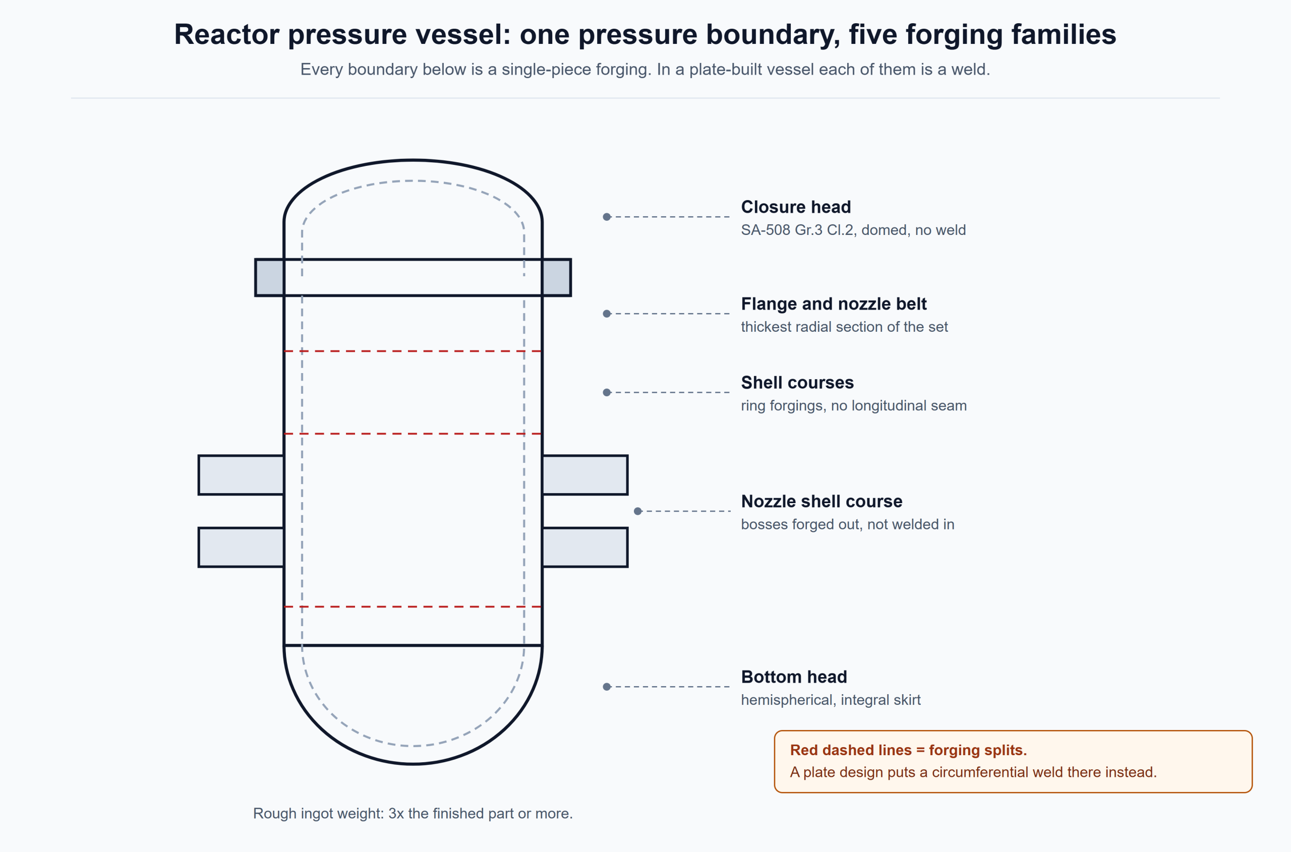
Five forging families make up the boundary: the closure head, the flange and nozzle belt, the shell courses, the nozzle shell course and the bottom head. Each one has its own thickness, its own reduction sequence and its own coupon position. Our RPV forgings page lists the grades and the size range; what this article is about is the part the drawing does not show.
The toughness requirement, written out
Toughness is the controlling property, and it is controlled through a fracture-mechanics framework rather than a single Charpy number. The reference temperature for the nil-ductility transition, RTNDT, anchors the whole lower shelf: once it is fixed by drop-weight testing, the Charpy requirements are specified at RTNDT + 33 °C, the temperature at which the material is required to be on the upper shelf.
Table 1. ASME SA-508 Gr.3 fracture toughness requirements — the shape of the specification
| Test | Property | Temperature | Requirement |
|---|---|---|---|
| Charpy V-notch, Cv | absorbed energy, single specimen |
−10 °C | ≥ 34 J |
| absorbed energy, three-specimen average |
−10 °C | ≥ 40 J | |
| absorbed energy | RTNDT + 33 °C | ≥ 68 J | |
| upper-shelf energy, average | — | ≥ 102 J | |
| lateral expansion | RTNDT + 33 °C | ≥ 0.90 mm | |
| Drop-weight test | no fracture | −10 °C (−20 °C lower shell) |
no break |
One specimen of the three is allowed to fall to 34 J provided the average still makes 40 J, which tells you how much the code expects scatter to matter. The upper-shelf figure of 102 J is the requirement that separates a well-forged ring from a merely acceptable one, because upper-shelf energy is where grain structure shows up most plainly.
National practice differs mainly in how far below zero the reference temperature is pushed. ASME does not fix a number and leaves it to the component duty, in practice between 0 and −10 °C. RCC-M requires a product reference RTNDT below −12 °C. German practice under KTA sets −12 °C in the active zone and 0 °C outside it. Chinese technical conditions add a grain size call-out on top of the toughness values: ASTM grade 5 or finer, checked as a separate acceptance item rather than as a process note.
Meeting the number is the floor. Every serious forging supplier works to a margin, because the customer re-tests, the irradiation programme shifts the transition temperature upward over life, and a ring that only just passes at −10 °C has no room for either.
What actually moves the transition temperature
Eight variables are usually listed as controlling toughness: chemical composition, microstructure, carbide morphology, degree of segregation, grain boundary purity, internal soundness, inclusion content and grain size. They are not equally available to a forging supplier.
Chemistry is set by the steelmaking route and by the standard — there is no room to move a SA-508 Gr.3 analysis far enough to buy toughness. What is left is structure: the size, shape, arrangement and orientation of the grains. Once the analysis is fixed, grain size becomes the dominant lever, and it moves FATT roughly linearly with the ASTM number.
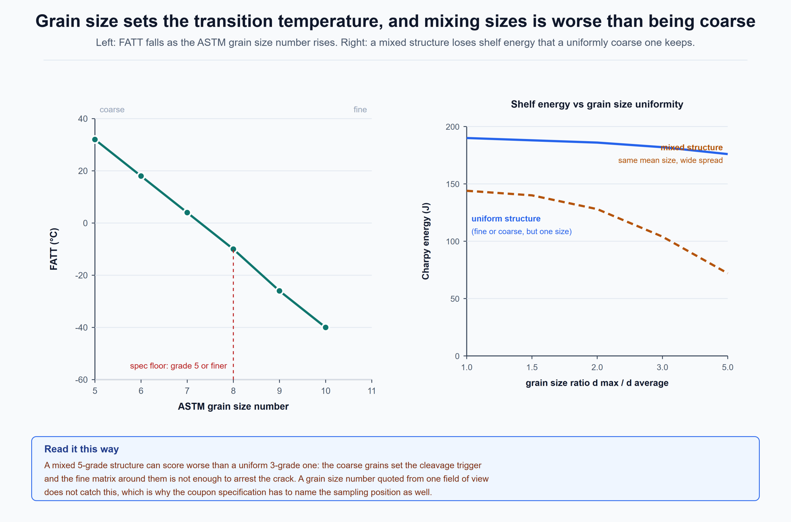
There is a second effect that a grain size number alone does not capture. A mixed structure — a few coarse grains embedded in an otherwise fine matrix — is worse than a uniformly coarse structure of the same average size, because the coarse grain sets the cleavage trigger and the surrounding fine matrix is not large enough to arrest the crack that starts there. Mixed grain is the classic signature of a forging that was worked unevenly: part of the section recrystallised and part of it did not.
This is why a coupon result can look acceptable and the part still be rejected on repolish, and why the sampling position belongs in the specification rather than in the supplier’s discretion. The metallurgy behind these structures is covered in more depth in our guide to the six basic steel microstructures.
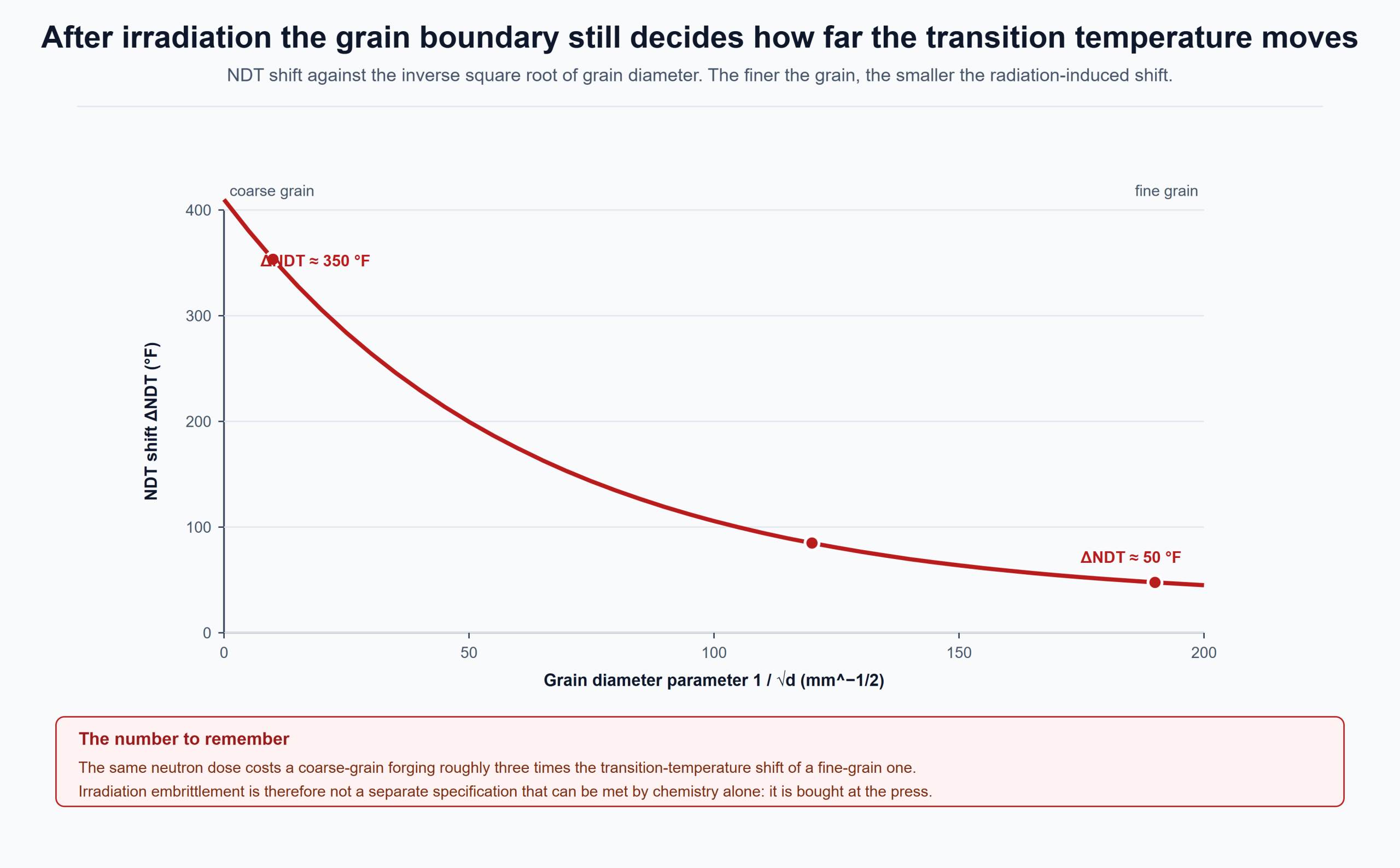
Grain size also governs how far the transition temperature moves under neutron exposure. The radiation-induced shift in NDT scales with the inverse square root of the grain diameter, so a coarse-grain forging pays roughly three times the embrittlement penalty of a fine-grain one for the same dose and the same copper and nickel content. A specification that treats irradiation as a chemistry problem alone has missed the variable that was decided at the press.
The ingot hands the forge a problem it cannot anneal away
Solidification sets the starting condition. In a cast ingot the metal freezes from the mould wall inward and from the base upward toward the hot top, so the cooling rate, the thermal gradient and the composition of the liquid all change as the front advances. The result is a structure that is not uniform anywhere: columnar dendrites at the surface, an equiaxed core, and a residual concentrate of solute, inclusions and shrinkage porosity along the axis and in the hot top.
Segregation is the stubborn one. Interdendritic liquid is enriched in carbon, sulphur, phosphorus and the alloying elements that partition to the liquid, and it freezes last in the spaces between dendrite arms. The larger the ingot, the longer the diffusion distance and the coarser the pattern. A 200 t ingot cannot be homogenised by soaking without also growing the austenite grain to a size that the rest of the route then has to undo.
Heat treatment does not rescue this, and the reason is structural inheritance. Chromium, nickel and molybdenum raise hardenability, which is wanted; but when the austenite grain coarsens, the transformation product inherits the outline of the prior austenite grain. A fine martensitic or bainitic structure produced from a coarse austenite grain still contains the coarse grain boundaries inside it, and those boundaries remain the weakest path through the material. You can refine the phase transformation product and still fail the grain size check.
So the only process step with enough thermal-mechanical authority to refine the structure is the press itself: deformation above the recrystallisation temperature, at a strain and strain rate that nucleates new grains, followed by a cooling path that keeps them. That is the whole argument for control forging. The same mechanism is visible in the melting stage of other alloy families — our note on VAR ingot structure in alloy 718 traces how melt rate sets the pool shape, the dendrite spacing and the resulting segregation.
Control forging: an outer loop for shape, an inner loop for structure
A large open-die forging is a hard process to control because the metal flow is three-dimensional, the temperature is falling throughout, and the tooling is simple. For most of the industry’s history the pass schedule was set by experience, corrected after the fact by the ultrasonic report. Control forging replaces that with an explicit model.
The distinction that matters is between external control and internal control. External control is geometry: does the part clean up, does it meet the drawing, does the press have the capacity. Internal control is what the acceptance test actually measures — whether the cavities have closed, whether the inclusions have deformed without cracking, what the grain size is, whether any internal crack was opened, and how much of the segregation pattern survived.
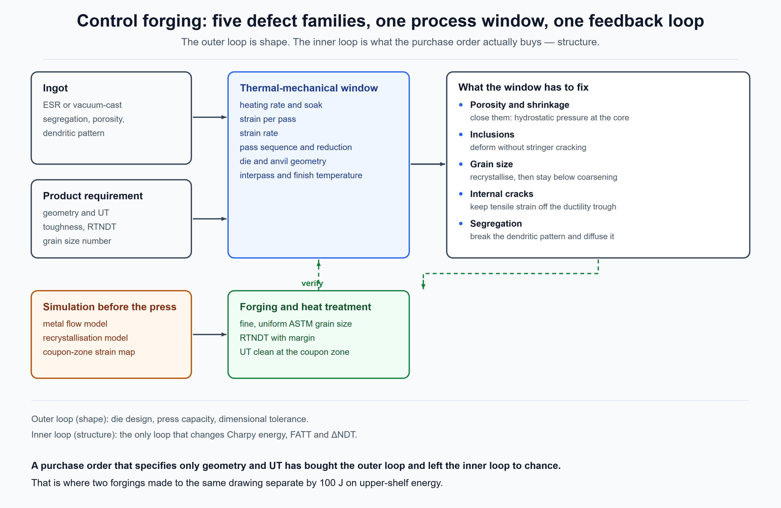
Five defect families have to be handled in the same pass schedule, and they do not want the same thing:
- Porosity and shrinkage. Closed by hydrostatic compressive stress at the core, which means the die contact geometry and the reduction per pass matter more than the total reduction.
- Inclusions. Cannot be removed by forging. The target is to deform them without opening stringer cracks, which sets a limit on how much local tensile strain the schedule is allowed to generate.
- Grain size. Refined by recrystallisation during the pass, then held by controlling the time above the coarsening range. The last pass and the time to the quench decide the final number as much as the first pass does.
- Internal cracks. Opened when tensile strain accumulates in the hot ductility trough. This is a strain-rate and temperature-window problem, not a reduction problem.
- Segregation. Broken up and diffused by working, which needs the dendritic pattern to be sheared across rather than simply compressed along.
Because those five pull in different directions, the pass schedule is a compromise that has to be simulated before the ingot goes into the furnace. A flow model gives the strain distribution; a recrystallisation model gives the grain size that follows from it; together they give a strain map of the coupon zone before any metal is cut. That map is what makes the difference between a schedule that is repeated because it worked once and a schedule that is known to work.
The upper flange: where the coupon is cut in the corner the press barely reached
The upper flange of a 300 MWe pressure vessel is the least forgiving part in the set. It is the thickest radial section and the shortest axial section, so the aspect ratio works against uniform deformation: the tools bear on the short dimension and the centre of the wall is the last place to receive strain. Its mechanical test coupon is taken at quarter depth near the inner-wall end of the ring — which is precisely the low-strain corner.
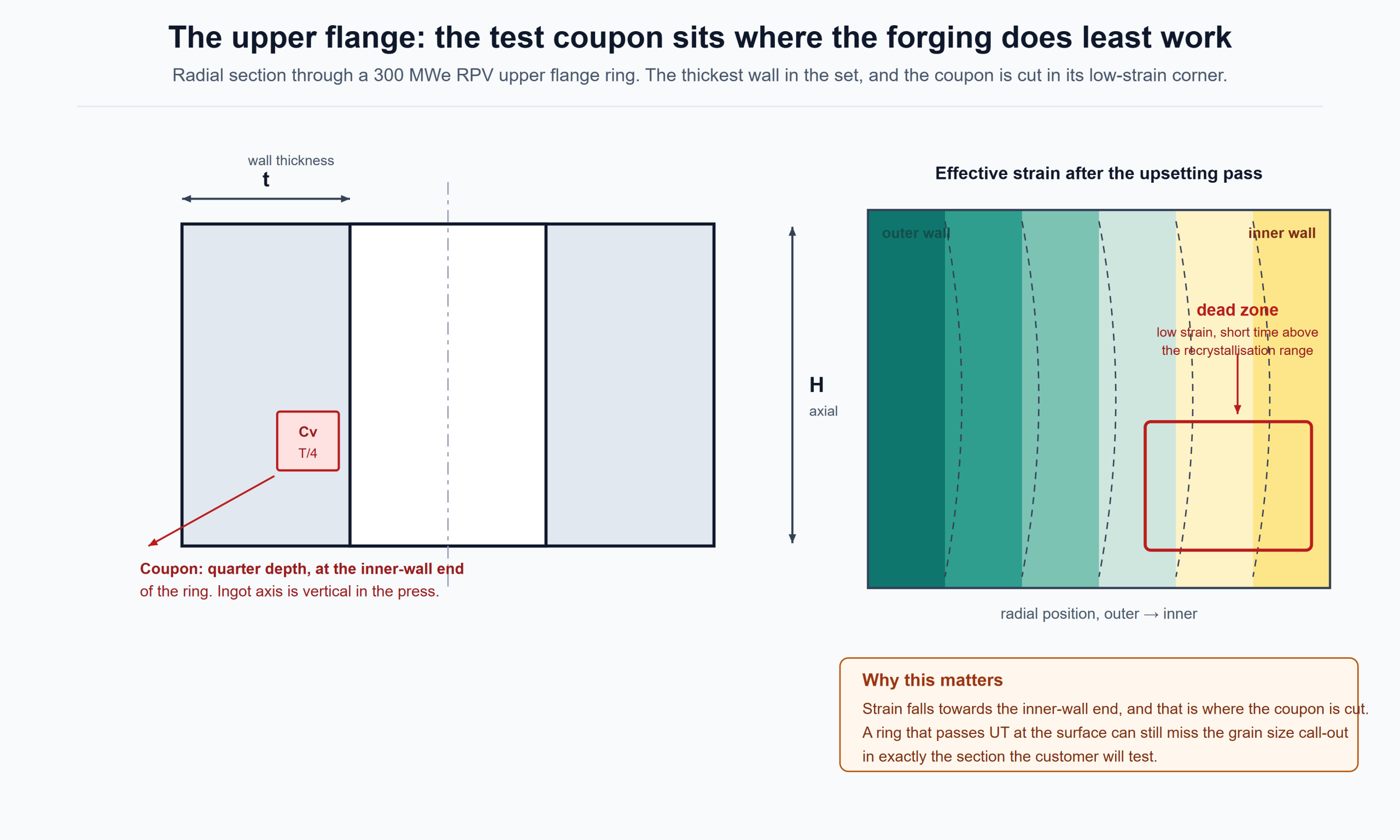
The requirement is therefore double. The forging has to eliminate the casting defects inherited from the ingot, and it has to deliver a fine, uniform grain structure in a corner that is geometrically shielded from the working. Reducing the ingot until the shape cleans up does not achieve the second, and increasing the reduction without changing the die geometry can make the first worse by opening internal cracks.
What changes the outcome is the sequence rather than the tonnage: an upsetting operation that puts the ring axis across the press, a punch-and-draw sequence that places the dead zone where the strain field is highest rather than lowest, a controlled turn between passes so the pattern is sheared in more than one direction, and a final pass hot enough and fast enough to leave a recrystallised skin. None of that shows on a drawing. All of it shows in the coupon.
For rings with a similar geometry the tooling logic is the same as on our nuclear flange ring forgings, where the wall is thin enough that the through-thickness gradient is not the limiting factor.
ESR changes the target, not the need for control
Electroslag remelting is standard practice for nuclear and hydrogen-service forgings, and on paper it solves most of the ingot problem. A 200 t ESR furnace delivers an ingot with low hydrogen, oxygen and sulphur; inclusions that are few, fine and dispersed, with a rating of 1.0 or better; and a slag skin that leaves the surface sound enough to forge without extensive conditioning. The hot workability is correspondingly good — a Ø2750 mm ESR ingot can take a 1000 mm reduction in the first pass without surface cracking, which no conventional cast ingot of that size will do.
Density tells the same story. Measured on a 26NiCrMoV 11 5 ingot, ESR material comes in at 7.840 g/cm³ against 7.805 g/cm³ at the core of a conventional ingot — a difference that is almost entirely the closed porosity the ESR process never allowed to form.
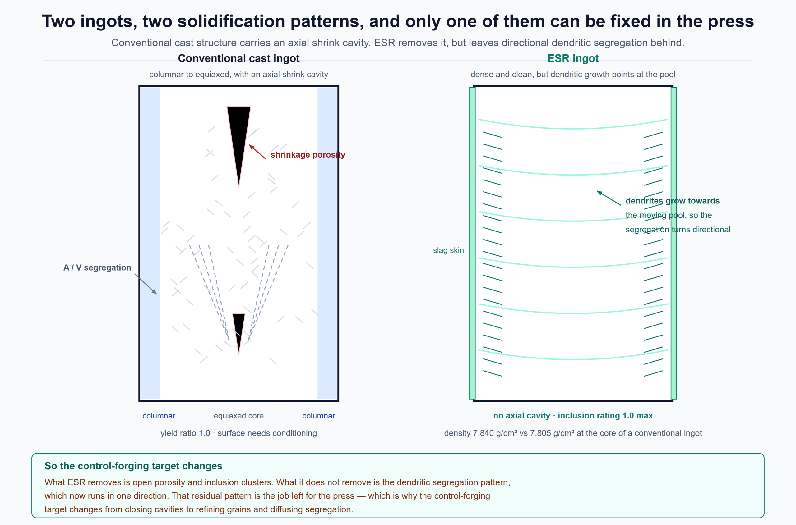
What ESR does not do is remove dendritic segregation; it re-arranges it. Solidification is directional — the pool advances upward and the dendrites grow toward it — so the secondary arm spacing is finer than in a cast ingot, but the dendrites are long and aligned. The segregation pattern that survives is therefore not a random scatter of enriched pockets but a directed pattern, and it has to be worked across its axis rather than along it.
That is why the control-forging target shifts for ESR stock. On a conventional ingot the first job is closing porosity and breaking up inclusion clusters; on an ESR ingot those jobs are already largely done, and the remaining job is grain size and the directional segregation pattern. Stated plainly: for ESR-fed nuclear forgings, control forging means grain size control and segregation improvement, and there is very little else left for it to do. The ring-forging side of that route is described under large seamless ring forgings.
What to put in the purchase specification
If grain size is the property that decides whether the part passes, then the specification has to name it, name where it is measured, and say what happens if it fails. A purchase order that specifies grade, dimensions and ultrasonic acceptance has bought the shape and left the structure to the supplier’s process discipline, which is exactly the variable that separates two otherwise identical rings.
Table 2. Acceptance items that decide whether a nuclear forging is actually controlled
| Item | Write this on the order | Why it matters |
|---|---|---|
| Grain size | ASTM E112, grade 5 or finer, coupon position named | a number without a position can be met by sampling the best zone |
| RTNDT | ASTM E208 drop-weight, plus Cv at RTNDT + 33 °C | anchors the whole lower shelf; cannot be inferred from room-temperature Charpy |
| Upper-shelf energy | average of three, ≥ 102 J, test location on the drawing | the only acceptance value that separates good forging from adequate forging |
| Ultrasonic | ASTM A388 / A745, acceptance level and scan surfaces stated | the coupon zone is not the only place where a dead zone can hide |
| Forging ratio | total and per-pass, with the reduction direction | ratio alone does not prove recrystallisation; direction does |
| Heat treatment | austenitising temperature, quench medium, tempering range, holding time | structure inheritance means the quench has to be matched to the prior grain size |
| Simulation report | strain and temperature map of the coupon zone, submitted with the offer | the cheapest way to see whether the schedule was designed or inherited |
| Certification | EN 10204 3.1 against the heat number, 3.2 where the code requires it | ties the coupon result to the piece that ships |
None of these items is unusual on a nuclear order. What is unusual is seeing all of them on the same document with the sampling positions drawn, and that is the difference between a specification that describes a forging and one that controls it. Two rings can pass every line of the first and still differ by 90 J on the upper shelf.
The short version
- A nuclear forging is bought at the coupon, not at the drawing. The coupon sits in the corner that receives the least work.
- Chemistry is fixed by the grade. Grain size is the only toughness lever a forge can still move, and it moves FATT about 15 °C per ASTM number.
- Mixed grain is worse than uniformly coarse grain, and it does not show in an average grain size number.
- Heat treatment cannot recover a coarse prior-austenite grain; the transformation product inherits the boundary.
- ESR removes porosity and inclusions but leaves directional segregation, so the control-forging target becomes grain refinement and segregation diffusion rather than cavity closure.
- Every one of these is a line item that can be written into the purchase specification. Most of them are not.
If you are specifying RPV or flange forgings in SA-508 Gr.3, 16MND5 or 20MnMoNi5-5 and want the coupon position and grain size call-out discussed before the drawing is frozen, send the section and the standard. We will come back with the reduction sequence and the strain map of the coupon zone, not just a price.
Related reading
- RPV forgings — the five forging families, grades and size range
- Nuclear flange ring forgings — thick-wall rings and their coupon positions
- Large seamless ring forgings — upset, punch and roll sequences
- Steel microstructure — the six structures that decide hardness and toughness
- VAR ingot structure in alloy 718 — how melt rate sets pool shape and segregation
You get chemical composition, mechanical properties and a price — with inspection certificates to EN 10204 3.1 issued against the heat number.