
Non-Destructive Testing Types (LP/MP/UT/RX)
Non-destructive test (abbreviated, NDT) used to evaluate the physical and mechanical properties of a welded connection without damaging the equipment. The most common non-destructive tests are visual inspection, penetrating fluids, magnetic particles, radiographic (RX) and ultrasonic examination (UT).
TYPES OF NON-DESTRUCTIVE TESTING
In this article, we review the most common non-destructive testing techniques used to examine welded connections (example: welded pipes, fittings or pressure equipment). Non-destructive tests do not damage the equipment being tests; destructive tests, instead, may damage the product.
Visual Inspection (VI)
Visual inspection is the simplest and the cheapest non-destructive test, and all welds must be subject to this basic method, using either the naked eye or a magnifying glass to confirm imperfections.
All surfaces to be visually examined must be thoroughly cleaned. This method is used only to detect surface imperfections.
If these are found, additional tests are employed to discover the extent of the flaw.
Even if a weld is to be examined by more-accurate methods of inspection, it should be subjected to the basic visuals, because of their low cost.
Also, if imperfections are detected visually, an additional examination can be intensified around this area of concern.
Liquid Penetrants (LP)
The liquid penetrant (or penetration) non-destructive test (LPE) is used on metals considered to be non-magnetic, such as austenitic- chromium stainless steel.
This technique requires the surface application of a penetrating liquid containing a dye. The liquid is given time to seep into any surface flaws, and excess liquid is removed. The surface is allowed to dry, and the weld is examined. Flaws are indicated by the presence of dye, which is visible to the naked eye.
Liquid penetrants are a low-cost test to detect cracks or abnormal porosity on the surface of the equipment.
Magnetic Particles (MP)
Magnetic particle examination (MPE) is a non-destructive used to detect surface cracks on ferromagnetic materials, such as carbon steel.
Some low alloys are magnetic, however, austenitic-chromium stainless steel is very weakly magnetic and therefore excluded from this type of examination; this is subjected to dye penetrant examination, which is covered later. The MPE method is very useful for detecting fine cracks that are invisible to the naked eye.
To carry out the examination, the weld under analysis is first strongly magnetized with an electromagnet, then fine particles of a magnetic material, such as iron or magnetic iron oxide, are applied to the surface. The magnetic powder is attracted to the edges of any surface cracks, making them visible to the naked eye.
Ultrasonic Test (UT)
Ultrasonic (UT) waves with a frequency of 500–5000 kHz are transmitted as a narrow beam toward a target. On reaching a metal surface with a flaw, the waves are reflected and returned to a suitable receiver. The time required for the return of the echo is a measure of the length of the path covered by the waves.
If used correctly, the ultrasonic method can approach the accuracy of radiography. The benefit of ultrasonic testing is that the equipment is portable; therefore, UT is useful when the weld is in an awkward location or needs to be examined on site.
Radiographic Test (RX or RT)
Radiographic (RT) examination is the most useful nondestructive test, as it detects subsurface flaws invisible to the naked eye.
This method originally employed X-rays, but today pipe joints can be examined using gamma-rays produced by portable radioactive isotopes. All sources of radiation are potentially dangerous, and exposure over extended periods must be avoided. Personnel protection is often a requirement for technicians carrying out the radiography.
A film is placed on one side of the weld, and on the other side, the weld is subjected to X-rays in the direction of the film. As the X-rays pass through the weld, any imperfections on the surface and through the weld are detected by a dark shadow on the exposed film.
No imperfection shows up as clear with uniform shade. The analysis of radiographic films requires considerable experience, and the defects that may be detected include cracks (surface and subsurface) and subsurface cavities caused by oxide film; lack of fusion; trapped slag, flux, or foreign material; and gas pockets (porosity).
Each radiograph must be recorded with the number of the weld to identify the exact location of the weld, and the names of the radiographer and inspector must also be listed. Radiographs are open to interpretation, and it is essential that the personnel used for this activity are suitably qualified.
Which method finds which defect
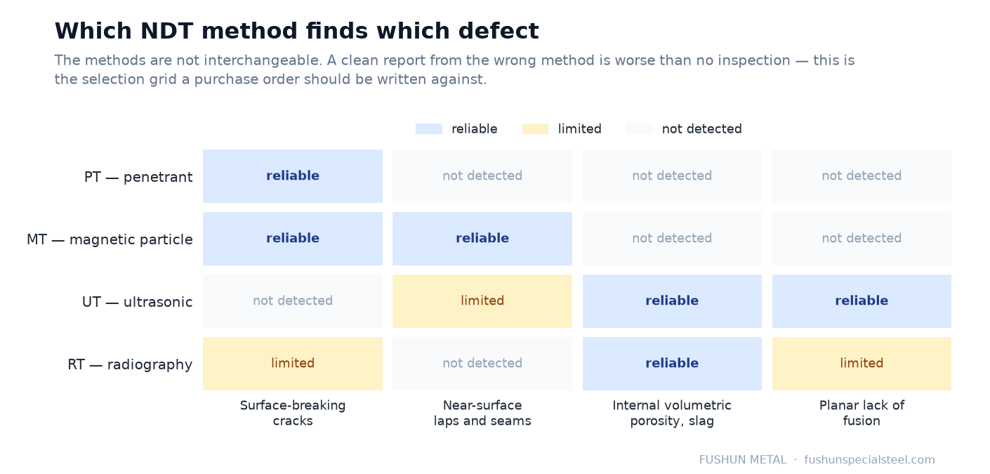
The four methods on this page are not interchangeable — each one sees a different class of discontinuity. Choosing the wrong one produces a clean report on a defective part, which is worse than no inspection at all.
For the full method write-up, see magnetic particle inspection; for the dye version, penetrant inspection.
The practical side of ultrasonic work is covered in how ultrasonic inspection works and ASTM A388 for heavy forgings.
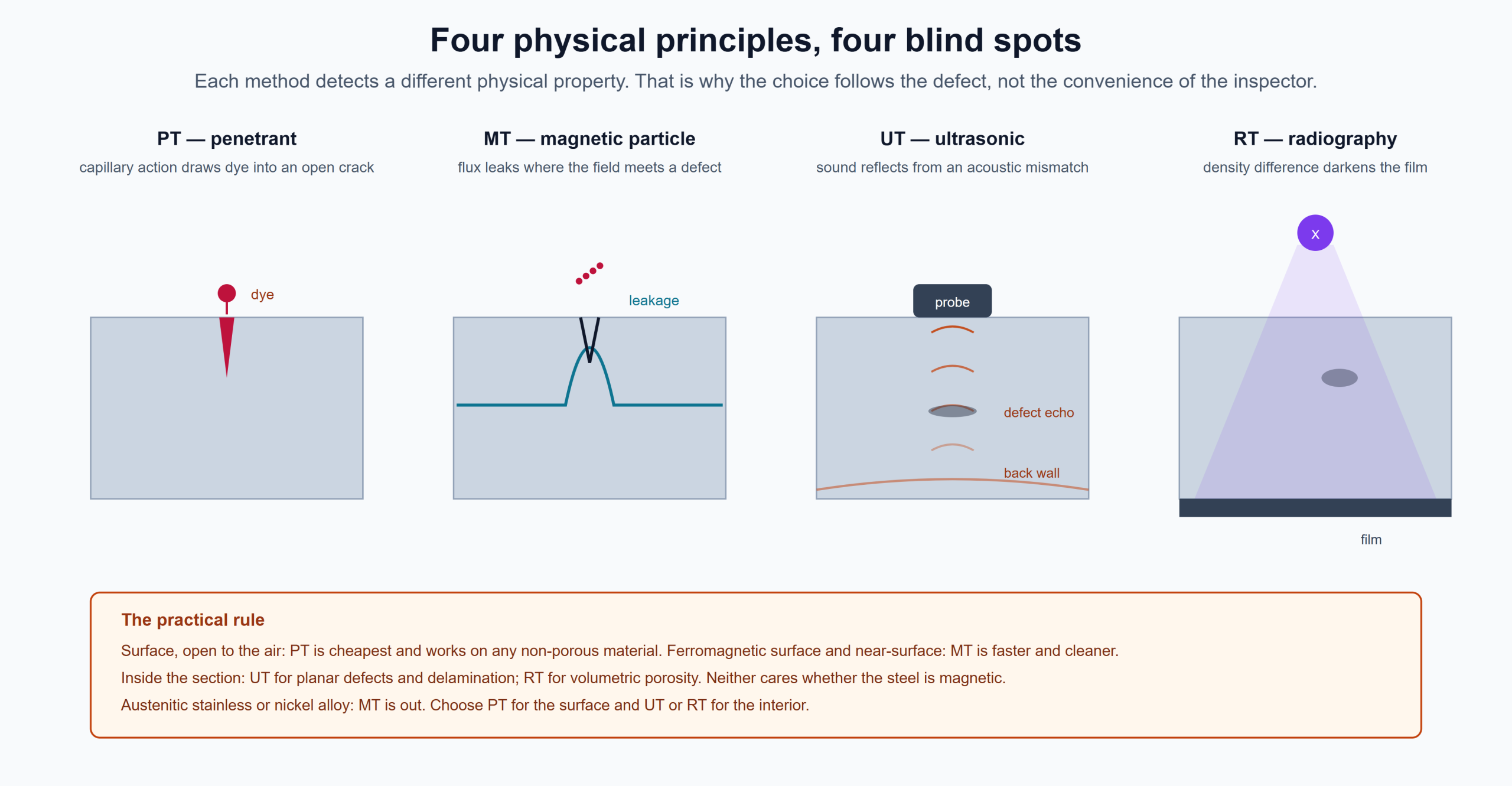
| Method | Finds | Material | Limitation |
|---|---|---|---|
| PT — penetrant | Surface-breaking cracks, porosity | Any non-porous solid | Nothing below the surface; surface must be clean and dry |
| MT — magnetic particle | Surface and near-surface cracks, laps, seams | Ferromagnetic only | Cannot be used on austenitic stainless or nickel alloys |
| UT — ultrasonic | Internal voids, inclusions, delaminations, lack of fusion | Most metals | Needs a couplant; geometry and coarse grain scatter the beam |
| RT — radiography | Volumetric voids, porosity, inclusions | Most metals | Radiation safety; poor at planar defects oriented across the beam |
The classic mis-selection
Ultrasonic testing on coarse-grained austenitic or nickel alloy weld: the grain boundaries scatter the beam and the result is a report full of noise, or a defect that is missed because the operator turned down the gain to quieten the screen. For austenitic welds the answer is usually radiography, or a qualified UT procedure with a dedicated reference block.
The mirror-image error is radiography on a tight lack-of-fusion in a thick section: the defect is planar and aligned with the beam, so the film looks clean while the joint is not.
What a purchase order should state
- The method and the standard (ASTM A388 for forging UT, A275 for MT, A609 for castings UT, AS 1710 for plate).
- The acceptance level — a method without a level is not a specification.
- The stage: raw material, after rough machining, or after final heat treatment. Defects introduced by heat treatment only show after it.
- Who interprets, and what happens when an indication is recorded.
Where NDT sits in the quality chain
Non-destructive testing verifies a process; it does not create quality. A forging that is ultrasonically clean is a forging whose melting, casting and forging practice were controlled. When a supplier offers “100 % UT” as a quality claim, the useful question is which acceptance level, at which stage, and what the reject rate has been.
Related reading
- Magnetic particle inspection — principles, methods and acceptance criteria.
- Penetrant inspection — the dye version, and where it stops.
- How ultrasonic inspection works — probes, couplant and the echoes that matter.
- ASTM A388 — the standard behind heavy forging examination.
You get chemical composition, mechanical properties and a price — with inspection certificates to EN 10204 3.1 issued against the heat number.