
Magnetic Particle Inspection (MPI): Principles, Methods and Acceptance Criteria
How the leakage-field principle finds surface and near-surface defects in ferromagnetic steel, which magnetization method suits which geometry, and how acceptance is actually decided against ASTM E1444, ASTM E709 and ISO 9934.
Magnetic particle inspection is the most widely used surface NDT method in steel manufacturing, and the one most often specified without the detail needed to run it properly. A drawing note that reads “MPI per ASTM E709” leaves the magnetization method, the current type, the particle carrier and the acceptance level undefined — and those four variables decide whether the test finds a 0.5 mm grinding crack or misses it entirely.
This guide covers the principle, the method selection logic, the process sequence and the acceptance framework, in the order a shop needs them. It applies to forged bar, plate, castings, weldments and finished machined parts in carbon, alloy, tool and martensitic stainless steels. It does not apply to austenitic stainless, aluminium, titanium or copper alloys — those are non-ferromagnetic and belong to penetrant testing or eddy current instead.
What Magnetic Particle Inspection Detects
MPI finds discontinuities that break the continuity of the magnetic path at or just below the surface: forging laps, seams, grinding cracks, quench cracks, fatigue cracks, weld toe cracks, porosity that reaches the surface, and inclusions that intersect it. It is fast, it gives an immediate visual indication, and it is far less sensitive to surface condition than dye penetrant.
Its limits are equally clear. It only works on ferromagnetic material. It is a surface method — practical detection depth is roughly 1–2 mm with direct current and less with alternating current, so internal defects need ultrasonic testing. It cannot size a defect in the through-thickness direction. And it is orientation-sensitive: a crack lying parallel to the magnetic flux produces almost no leakage field, which is why every procedure requires magnetization in at least two directions roughly 90° apart.
The Leakage-Field Principle
When a ferromagnetic part is magnetized, the magnetic flux travels through the steel along paths of least reluctance. A crack, lap or inclusion has a much higher reluctance than the steel around it, so the flux is forced out of the surface, travels through the air across the discontinuity, and re-enters on the other side. That external field is the leakage field.
Magnetic particles applied to the surface are attracted into this field and accumulate at the defect, forming an indication that is visible under suitable lighting — typically two to three times the physical width of the defect, which is why MPI can reveal cracks far too narrow to see with the naked eye. The indication is a surface phenomenon, not a photograph of the defect: it depends on the defect being open enough to produce a field, which is why a tight crack that has been peened shut may not indicate.
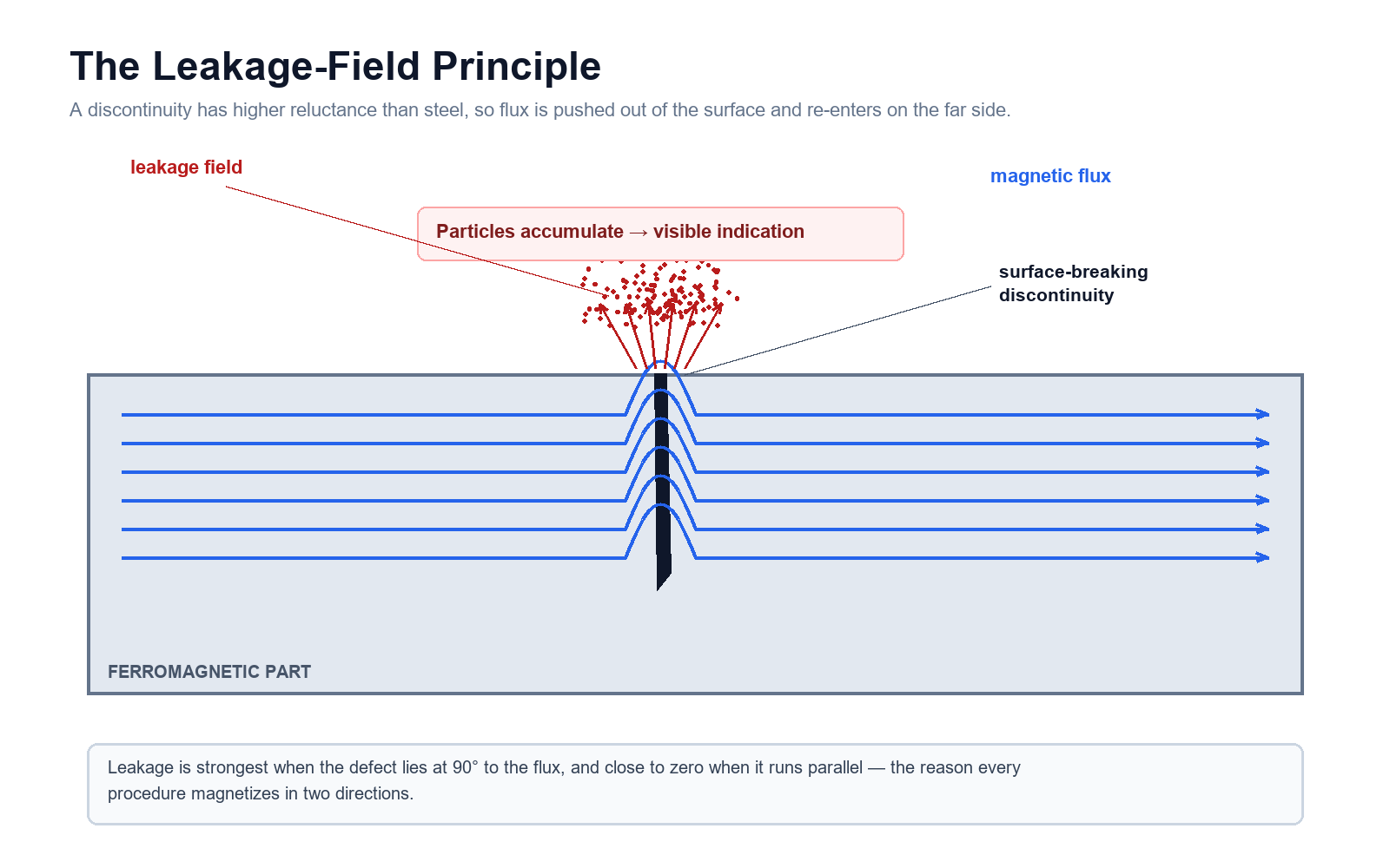
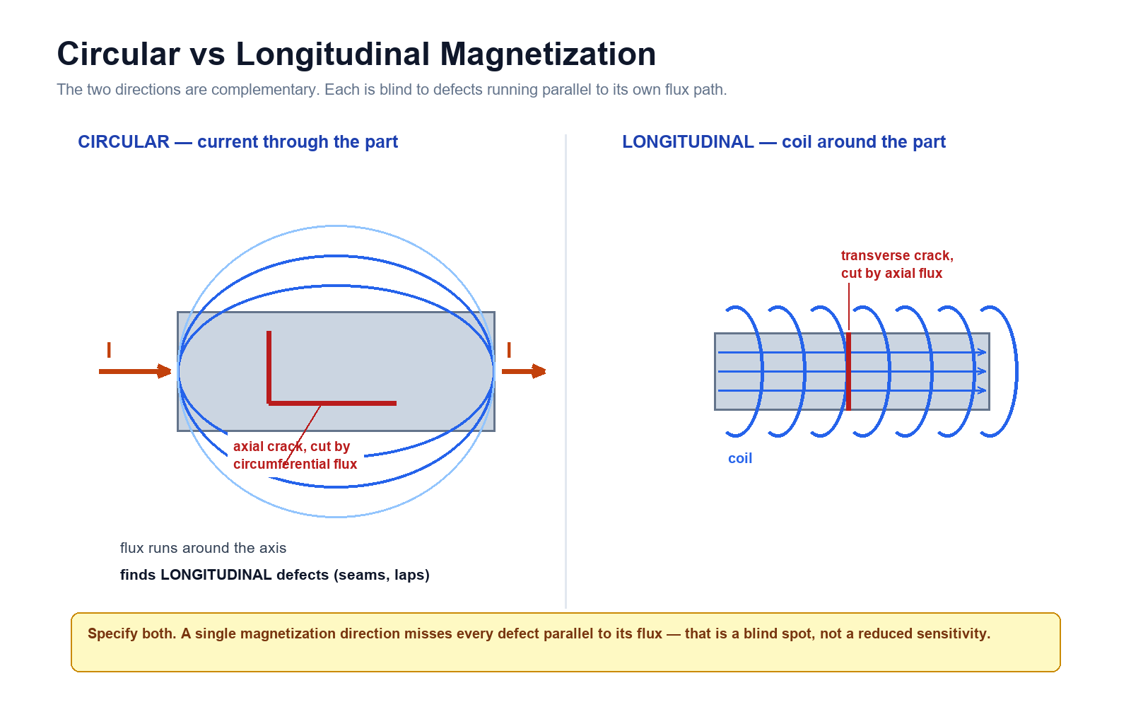
The orientation rule follows directly. A defect produces the strongest leakage field when it lies at 90° to the magnetic flux, and almost none when it lies parallel. Since crack orientation in a forging or a weld is not known in advance, the procedure has to magnetize in two directions at right angles — circular plus longitudinal, or two circular directions on a part with complex geometry.
Magnetization Methods
Magnetization is described by the direction of the flux it produces relative to the part axis, and by the way the current is applied. Both matter, and they are chosen independently.
Circular magnetization passes current directly through the part or through a central conductor, producing a field that runs circumferentially around the current path. It finds longitudinal defects — seams, laps, and cracks running along the axis of a bar — because those defects cut across the circumferential flux. The contact method uses the part itself as the conductor; the central conductor method is used for rings, sleeves and hollow parts where contact would be impractical or would arc.
Longitudinal magnetization uses a coil or a magnetic yoke to drive flux along the part axis. It finds transverse defects — circumferential cracks, forging bursts, and transverse weld cracks. The yoke is the field-work method of choice for weld inspection because it is portable, needs no electrical contact with the part, and can be positioned on either side of a weld cap.
Composite and rotational magnetization combine the two by feeding two phases or by rotating the field, producing a resultant flux vector that sweeps through 360° in a single pass. It is faster and it removes the second-pass labour, but the equipment is more complex and the field strength in each direction is lower than a dedicated single-direction setup.
| Method | Flux direction | Finds best | Typical parts | Limitation |
|---|---|---|---|---|
| Direct contact (head shot) | Circular | Longitudinal seams, laps, axial cracks | Bar, tube, shaft ends | Arcing and burning at contact points; needs clean contact faces |
| Central conductor | Circular | Bore and inner-surface defects, longitudinal cracks | Rings, sleeves, hollow forgings | Field strength falls with distance from conductor |
| Prod (contact probe) | Circular, local | Local surface cracks, weld toes | Weldments, large castings | Only the area between prods is inspected; arc burns possible |
| Coil / cable wrap | Longitudinal | Transverse cracks, forging bursts | Bar, shafts, long parts | Field falls off toward part ends; effective length is limited |
| Magnetic yoke | Longitudinal, local | Transverse and angled surface cracks | Welds, castings, field inspection | Limited to what fits between poles; lifting-force check required |
Table 1 — Magnetization methods and the defect orientation each one is chosen for.
Current Type: What AC and DC Actually Change
Current type controls how deep the flux penetrates. Alternating current concentrates in a thin surface layer through the skin effect, so practically all of the magnetizing field sits within about 0.5 mm of the surface. It is the right choice for finish-machined parts and for finding fine grinding cracks, and it is the easiest to demagnetize afterwards.
Direct current and full-wave rectified DC produce flux through the full section, so they reach near-surface defects that AC misses. Half-wave DC sits between the two and has a practical advantage: the pulsating current vibrates the particles slightly, which helps them migrate to the leakage field on rough or vertical surfaces. The cost is that DC magnetizes deeper and demagnetization becomes correspondingly harder.
| Current | Effective depth | Best for | Demagnetization |
|---|---|---|---|
| AC | ~0.5 mm (skin effect) | Finish-machined surfaces, fine grinding cracks | Easy |
| Half-wave DC (HWDC) | ~1 mm | Rough surfaces, vertical faces, near-surface defects | Moderate |
| Full-wave DC / rectified | ~1.5–2 mm | Subsurface discontinuities in heavy sections | Harder; may need coil decay |
Table 2 — Current types and their penetration. Depth figures are practical working values for steel, not theoretical limits.
Wet or Dry Particles
The carrier decides the sensitivity and the surface condition the method tolerates. Wet particles are suspended in a liquid vehicle, applied by spray or flow, and are the choice for smooth machined surfaces and fine defects. Dry powder is applied by a hand-held bulb or a compressed-air gun and is better on rough castings, at elevated temperature, and where the part cannot be wetted.
Fluorescent particles are used with ultraviolet light in a darkened booth. Against a black background, a fluorescent indication has far higher contrast than a black particle on steel, which is why the aerospace standards default to it for critical parts. Visible-dye particles — usually red or black — are used under white light where a darkened booth is not available.
Lighting is a specified part of the test, not a convenience. Visible-light inspection needs at least 1000 lux at the surface, and fluorescent inspection needs less than 20 lux of ambient white light with a UV-A intensity of at least 1000 µW/cm² at the inspection surface. A procedure that does not state these values cannot be audited.
The Process, Step by Step
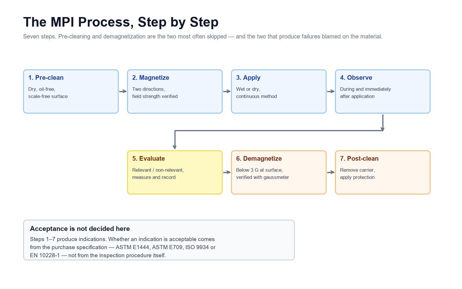
1. Pre-cleaning. The surface must be dry, free of oil, grease, scale, paint and loose rust. Contamination prevents particles from reaching the leakage field and produces false indications. Cleaning method matters — blasting can peen a tight crack closed and hide it, so parts that will be blasted should be inspected before, not after.
2. Magnetization. Set the current from the part diameter or the coil turns, using the formula or the calibrated curve in the applicable procedure, and verify with a field indicator or a Ketos ring. A yoke must be checked for lifting force before each shift — typically 4.5 kg at the specified pole spacing.
3. Particle application. Apply while the part is magnetized (continuous method) or immediately after the current is switched off (residual method). Continuous is more sensitive and is the default for critical work; residual is used where the magnetizing equipment and the application station are separate.
4. Observation. Inspect during application and immediately after, before the particles drain or settle. Look for indications that form, hold their shape and resist light rinsing — those are relevant. Indications that wash away or re-form elsewhere are usually non-relevant.
5. Evaluation and recording. Classify each indication, measure its length, and record its location. Photograph critical indications before demagnetization washes the contrast away.
6. Demagnetization. Required whenever residual magnetism would interfere with subsequent machining, welding, or service — and always for parts that will be returned to a rotating machine. The usual acceptance limit is 3 G (0.3 mT) at the surface, measured with a gaussmeter; some aerospace specifications call for 2 G.
7. Post-cleaning. Remove residual particles and carrier, then apply the specified corrosion protection. Wet-method parts that are left wet will rust, and the rust will be attributed to the material rather than to the process.
Reading Indications: Relevant, Non-Relevant, False
Not every mark on the surface is a defect, and the distinction is where inexperienced inspection goes wrong in both directions — rejecting sound parts and accepting cracked ones.
Relevant indications arise from an actual discontinuity. They tend to be sharp, well defined, and repeat at the same location when the part is re-magnetized. Non-relevant indications arise from geometry: a sharp change in section, a keyway, a thread root, a weld toe, or the edge of a hole all concentrate flux and produce a legitimate indication from a sound part. They are recognised by their location and by the fact that they follow the geometry rather than crossing it. False indications come from the process itself — magnetic writing from particles dragged across the surface by a probe, or residue left by a contaminated carrier.
The practical rule is to re-examine any doubtful indication after demagnetizing and re-magnetizing at a slightly different current. A real crack returns in the same place; a magnetic writing artefact does not.
Acceptance Criteria
Acceptance is written into the purchase specification, not into the inspection procedure, and it differs sharply between market sectors. Aerospace work under ASTM E1444 is the most demanding; general industrial work under ASTM E709 or ISO 9934 is more permissive; forging specifications such as EN 10228-1 define quality classes by defect length and location.
Most acceptance standards work from the same two categories. Linear indications — length at least three times the width — are treated as cracks and are generally rejectable above a stated length. Rounded indications are treated as porosity or inclusions and are judged by diameter and by clustering. Both are assessed against the surface finish and the criticality of the region: a 1.5 mm indication on a machined bearing journal and the same indication on a rough casting are not equivalent.
For buyers, the useful discipline is to state the acceptance standard, the quality class and the inspection coverage in the purchase order — “100 % MPI of the bar surface, EN 10228-1 class 2, longitudinal and transverse magnetization, wet fluorescent, report with indication map”. That sentence prevents most of the disputes that arise after delivery.
Where MPI Sits Among the NDT Methods
MPI, penetrant testing, ultrasonic testing and radiography answer different questions and are rarely substitutes. Penetrant testing finds surface-breaking defects on any non-porous material including austenitic stainless and aluminium, but only those open to the surface. Ultrasonic testing finds internal defects and measures wall thickness but is poor on small surface cracks. Radiography images internal volumetric defects and is largely blind to tight planar cracks oriented parallel to the beam.
For steel bar and forgings the usual combination is MPI for surface and near-surface, plus ultrasonic testing for the interior. Our overview of non-destructive testing types (LP, MP, UT, RT) sets out how the four methods divide the work, and the ultrasonic side is covered in more depth in our note on steel bar ultrasonic testing in coarse-grain grades.
Grade selection changes what the inspection is looking for. Martensitic stainless steel grades are prone to quench cracks and grinding cracks that MPI detects readily, while heat-resistant steels in heavy sections are more likely to show forging-related indications that need ultrasonic confirmation of depth.
Equipment Checks That Decide the Result
Three checks separate a procedure that works from one that merely satisfies the paperwork. They should be performed at the stated interval and recorded, because in a dispute the record is the only evidence that the test was valid.
Yoke lifting force. With the poles at the specified spacing, an AC yoke must lift a 4.5 kg steel block. This is a check on the yoke, not on the part, and it catches a failing coil before it produces a shift of false accepts. Perform it at the start of every shift.
Field strength and direction. A pie gauge or a Ketos ring placed on the part confirms that the magnetizing current in use actually produces adequate flux at the surface and in the required direction. Current calculated from a formula is a starting point; the indicator is the proof.
Particle concentration and contamination. Wet-method suspension is checked by settling volume — the particles in a 100 ml sample must settle to the specified volume after the stated standing time. A carrier that has been in service too long accumulates iron and produces a background that masks small indications, which is the failure mode most likely to be missed on a routine audit.
Common Pitfalls
Inspecting after blasting. Peening closes tight cracks and hides them. Inspect before surface preparation, or re-open the surface afterwards.
One direction only. A single magnetization direction misses every defect parallel to its flux. Two directions 90° apart is the minimum, not a refinement.
Insufficient current. Under-magnetization gives weak indications that look like non-relevant marks. Verify with a field indicator rather than by eye.
Contaminated carrier. Reused wet-method fluid accumulates iron particles and produces background noise that hides small indications. Check the settling test at the specified interval.
No demagnetization. Residual magnetism attracts chips during machining, deflects welding arcs, and in service can interfere with instruments and bearings.
Frequently Asked Questions
Can MPI be used on stainless steel? Only on ferromagnetic grades — martensitic and ferritic types such as 410, 420, 431 and 17-4PH. Austenitic grades 304, 316 and 321 are non-magnetic and require penetrant testing instead.
How deep does MPI penetrate? Roughly 0.5 mm with AC, 1–2 mm with direct current. It is a surface and near-surface method, not a volumetric one.
What is the difference between MPI and DPI? MPI uses a magnetic field and works only on ferromagnetic materials but detects near-surface defects. DPI uses a coloured or fluorescent liquid and works on any non-porous material but detects only defects open to the surface.
Does MPI damage the part? Not inherently, but contact methods can cause arc burns if the contact faces are dirty or the current is applied before the heads are seated — and those burns are themselves rejection criteria.
What We Supply
Fushun Special Steel supplies forged bar, plate and machined components in carbon, alloy, tool and martensitic stainless grades, with MPI and ultrasonic testing performed to the specification stated on the order. Where a part is destined for a regulated application, we can supply the indication map, the inspector certification level and the third-party witness report alongside the mill certificate. Details of the grades we hold in stock are on the tool steel and nickel alloy trade name pages.
You get chemical composition, mechanical properties and a price — with inspection certificates to EN 10204 3.1 issued against the heat number.